The Rpm Chronicles
The RPM Chronicles
TDC
Kevin Cameron
EARLY INTERNAL-COMBUSTION ENGINES weighed a hundred or more pounds per horsepower. Reasons? They resembled the dominant power source of 1860, the steam engine. Major parts were cast in gray iron, cranks turned once or twice a heartbeat and combustion pressure was feeble.
Design paused at this stage while the basic problem of ignition was solved. It took time for the reliability of electricspark magnetos to overtake and surpass that of open-flame or hot-tube igniters. Magnetos eliminated flame transfer delay, allowing rpm to rise into the hundreds. Engine bearings were like those in steam engines and railroad axles: bronze inserts bored to fit the journals. Stress and speed were so low that such engines ran for decades.
Otto’s four-stroke cycle plus charge compression removed the limits to combustion pressure. By 1900 it was clear that here was the future of transportation. Engines now weighed 20-40 pounds per horsepower.
Even so, the Wright brothers found no engine in 1903 light enough to power their airplane. They built one-much of it machined from solid to control metal thickness and weight. The crankcase was aluminum, the strange new metal. Performance was marginal, but specific power was remarkable, at 10-12 pounds per horsepower.
In 1914 the airplane went to war, so governments burned money to improve its powerplant. The German system, pioneered by Mercedes and widely copied, was to weld extremely light water-cooled cylinders from thin sheet steel. The dominant form was six of these separate cylinders, bolted to an aluminum box crankcase. Bearings had evolved to become brass inserts plated with white, low-melting-point bearing metal, or babbitt. Its softness allowed hard wear particles in the oil to embedhammered down below the bearing surface where they were harmless.
At the start of WWI, although weight was low, rpm was limited to about 1400 by the vigorous motion, or “weave,” of the individual cylinders as they fired, twisting the light crankcase and misaligning the bearings. Such engines weighed 4-5 pounds per horsepower.
The Marc Birgikt-designed V-Eight engine of the French Spad fighter plane was water-cooled, with cast aluminum cylinder blocks bolted to a cast case. The cast blocks of four cylinders stiffened the crankcase, allowing these engines to run at 1800 rpm. By 1918, these engines weighed just over 3 pounds per horsepower.
During the 1920s and ’30s, repeated attempts were made to cast aluminum cylinder blocks and crankcases in one rigid unit. Each time, high scrap rates forced construction back to separate parts.
Attempts in racing to operate engines at higher rpm resulted in melted-out bearing white metal. It was then realized that bearing journals needed oil not only for lubrication, but also for cooling. Bearing inserts had to be in tight thermal contact with the surrounding structure, providing a solid heat path. Fullpressure oiling systems replaced crude dipper or splash systems.
In automobile racing, engine rpm rose toward 6000 between the wars, exerting heavy inertia loads on bearings. The normally used thick layers of soft bearing metal cracked from surface fatigue. Thinner layers of white metal, backed by brass or steel, survived heavier loads.
Designers gained experience with every new design. Engine structure was improved as foundry technique mastered the problems of making large, complex castings. By 1945, aircraft engines had reached 1 pound per horsepower.
Poor valve action is the enemy of higher engine rpm. Formal analysis revealed that best-guess cam profiles were shocking mechanical parts with instant changes of acceleration that no material could withstand. Subtle changes to profiles softened these acceleration changes so that springs and valves could survive at higher rpm. Another important technique-reduction of valvetrain mass-had long been appreciated. High-speed engines operated their valves with as few parts between cam and valve as possible. Rocker arms and pushrods were eliminated by moving camshafts from their original position in the crankcase up to a new position above overhead valves.
Early crankshafts broke as speeds rose. Larger inertia and pressure forces excited torsional vibrations at particular speeds. This rapid twisting accumulated stress cycles so fast that cranks died of fatigue. Simple analysis showed that the lighter the crank, the higher its natural torsional frequency-perhaps high enough to be above the engine’s firing frequency. Cranks were now made hollow wherever possible-removing weight with little loss of stiffness. Various kinds of vibration dampers or absorbers were devised. As a result, cranks could be designed to operate at almost any desired speed.
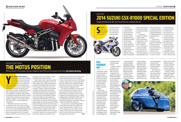
Although partly offset by rotating counterweights, reciprocating inertia forces increase as the square of rpm. Because increased rpm is a main pathway to power, it brings with it increased crankcase flex. In engines with separate cylinder and crankcase castings (like the classic Kawasaki Z-l ), this case flex produces scrubbing motions at the cylinderto-case gasket surface, causing oil leakage and stud breakage. The best way to increase engine stiffness was to do what so many tried and failed to do back in the ’20s and ’30s: Cast the upper crankcase and cylinder block(s) in one self-bracing unit. Production motorcycle engines adopted this configuration in the late 1980s, although pure racing engines had been built this way 25 years before.
What next? Stress in high-revving piston engines comes mainly from the forces arising from the back-and-forth motion of pistons and rods. Future supersport production motorcycle engines will probably seek to reduce this with titanium connecting rods, rather than simply overpower it with the more expensive stiffness of crankcases cast from aluminum-beryllium alloys. Of course, if we could predict the future, it would already have happened. U