Tuned Exhaust For the Two-Stroke
TUNED EXHAUST FOR THE TWO-STROKE
UNQUESTIONABLY, the best reason for the revival of two-stroke racing engines is the expansion-chamber exhaust system. This device, a fairly recent development, is largely responsible for the fantastically high specific power output of the modern racing two-stroke, and it should be obvious to everyone that tuners working with the “valveless wonders” will need to know something about these expansion chambers. Unfortunately, while everyone knows how important the expansion-chamber exhaust system is, few know anything at all about how it works, or how to design one for some particular engine. The fact that the expansion-chamber exhaust system exists, and does the job, is proof positive that there are people who do understand its workings, but they have not been too willing to pass any of their knowledge along to the rest of us.
Having been a dabbler in two-stroke speed tuning for many years, the lack of specific information regarding the expansion chamber exhaust system has been a particular problem for me. My answer has been to gather every scrap of information that has been made available on this subject; drawing from books, magazine articles and engineering papers. In this manner, I have constructed what I fancy to be a rational explanation of what the expansion-chamber does, how it does it, and how the various sections of the system should be proportioned. It may be that my conclusions are entirely wrong; but my design method seems to check rather well against existing, successful racing two-strokes, and an expansionchamber system designed along lines I presume to be correct certainly did a lot for my Villiers-engined Cotton Telstar. Of course, only time, and the repeated application of the method to all types of two-strokes, will tell if my conclusions are correct.
Before we get into a discussion of The Method, it might be wise to review some of the fundamentals of wave behavior in pipes. First, you should know that waves can have either positive or negative values: the former being a condensation of molecules in the gas through which the wave travels; the latter a rarefaction. Roughly speaking, it can be said that a wave is a low-pressure or high-pressure area moving through some medium — in the case we are discussing: exhaust gases. In the open, a wave will radiate out in all directions, as when you toss a stone in a pond; trapped in a pipe, it will travel along the pipe until it reaches the end. Should the end of the pipe be closed, the wave will bounce back without changing value: a positive wave will be reflected as positive wave; a negative wave likewise. However, if the end of the pipe is open, the wave will be reflected with an opposite value: a positive pressure wave will be returned back up the pipe as a negative wave, etc. In an expansion-chamber type system, we will make use of this reflected wave phenomenon.
Another device that should have some explanation is the megaphone. Many years ago, when it was first discovered that the negative reflection of a positive exhaust pulse could be used to scavenge residual exhaust gases from a cylinder, some bright lad reasoned that if a second, slightly larger diameter pipe were added to the primary exhaust pipe, then there would be a negative reflection when the exhaust pulse reached the end of the first pipe, and another when the same pulse reached the end of the second, larger diameter pipe. By making the second pipe very short, the second negative reflection was returned virtually overlapping the first, and in effect, there was a single negative wave of fairly long duration coming back up the pipe to scavenge the cylinder. From that point, it was only logical to add a third section of pipe, still larger, and then a fourth, while crowding the stepped sections closer together. Carry this to its conclusion, and you have a megaphone.
In an exhaust system fitted with a megaphone, the exhaust pulse begins to be reflected as a negative pressure wave as soon as it passes into the megaphone, and it continues to reflect until the end of the megaphone is reached. Of course, as the initial positive pulse travels down the megaphone, its energy is dissipated in creating the reflected negative wave, and by the time the wave has reached a point in the megaphone where the crosssectional area is approximately six times the area of the lead-in pipe, so much of the energy will have been lost that there is no point in taking the wave any further and the megaphone can be ended. You might also be interested to know that the wave reflected by a short, wide-angle megaphone has a high amplitude, or strength, but of short duration. Longer, slow-taper megaphones return a wave of lesser amplitude, but correspondingly increased duration. Incidentally, the slow-taper megaphone is more efficient in recovering the energy of the initial pulse, and as it also prolongs the duration of the reflected wave (which means that it will be effective over a wider engine speed range), this type of megaphone usually gives the best overall performance, even though not necessarily the highest maximum power. Because the racing twostroke tends to have a very narrow power band in any case, the slow-taper megaphone is the only one worth consideration. Short, wide-angle megaphones have been used on scramblers, without an expansion chamber tacked on behind, but it may safely be assumed that this type of two-stroke exhaust system is a creature of convenience, not science, and should be avoided.
Now then, the next phase of this discussion may as well be a description of the expansion-chamber system, and what function is served by its various sections. First, there is the lead-in pipe; then comes the divergent cone; followed by a convergent cone (there may or may not be a straight section between the two); and finally the chamber’s outlet pipe. The lead-in pipe merely serves as a passage to carry the exhaust to the divergent cone, which operates in the same manner as any megaphone. It is important that the lead-in pipe be the correct length: make it long enough so the exhaust pulse will have just enough time to get down to the megaphone and reflect back up to the exhaust port as a negative pressure wave just as the transfer ports are uncovered by the piston. This will create a negative pressure in the cylinder that not only pulls out residual exhaust gases, but helps the fresh charge to flow into the cylinder from the transfer ports.
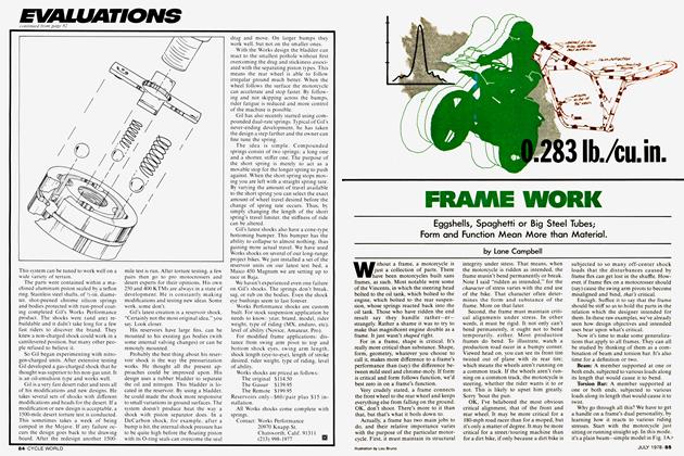
If the exhaust system was terminated there, part of the fresh charge would be pulled right out the exhaust port. To prevent this, we add to the system a convergent cone, which partially closes the end of the chamber and forces the exhaust pulse emerging from the megaphone to reflect back as a positive pressure wave. It is this reflected positive pressure wave (which gathers strength and speed as it travels up the megaphone) that picks up whatever part of the fresh charge that may have escaped into the lead-in pipe and forces it back into the cylinder. This wave also gets some help from the restricted capacity of the expansion chamber. When the exhaust slug slams down into the chamber, it expands and causes a pressure rise inside the chamber. Because the chamber outlet is restricted, the rising pressure helps to pick up the fresh mixture that is trying to escape and stuffs it back into the cylinder. In this regard, the diameter (and to a lesser extent the length) of the outlet pipe is important, as the smaller the outlet pipe area is, the higher and more rapid will be the pressure rise inside the chamber. In general, it may be said that large-volume (relative to cylinder displacement) expansion chambers should have small outlet pipes; and of course the reverse is true, too.
GORDON H. JENNINGS
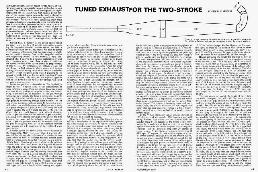
Probably the best means of reducing all this to a method anyone can use to design an expansion chamber exhaust system for a two-stroke is to do just that: design an expansion chamber exhaust system for a two-stroke. And, rather than use a hypothetical example for which there is no real application, we will use the Villiers Starmaker engine. This engine is becoming more and more widely used, and I have measured the port heights and know what the port timing is — which is a bit of knowledge essential to my own method of two-stroke exhaust system design.
In the Villiers Starmaker engine, exhaust duration is 160 degrees, and the transfer 120 degrees (very mild timing indeed). This means that the exhaust leads the transfer phase by 20 degrees, as the timing is split symmetrically on each side of bottom center, so our lead-in pipe will have to be the correct length to return a negative reflection from the divergent cone after 20 degrees of crank rotation. At the Starmaker engine’s power peak of 6500 rpm, 20 degrees of crank rotation represent a time of .00051-seconds. Through most of the exhaust system, we can use a wave speed of 1700 feet per second, but the very high temperature and velocity of the exhaust gases as they leave the port give us an effective wave speed of probably 3500 ft/sec for the first foot or so of travel. So, what we must do is provide a lead-in pipe of a length sufficient to allow the initial pulse to travel down to the divergent cone, and be reflected back as a negative pressure wave that will reach the cylinder just as the transfer ports open. A wave traveling at 3500 ft/sec will cover 1.785 feet in the .00051-second time interval provided by the 20-degree exhaust lead, and we then cut that distance in half, as the wave is making a two-way trip, down the lead-in pipe and then back. This gives us a length of 10.71" for the lead-in pipe. We should point out that since this figure is based on an assumed wave speed of 3500 ft/sec, which is only a close approximation, there is no point in carefully trimming the pipe to the exact dimension; get within an inch and that will be close enough.
Having calculated the length for the lead-in pipe, it is now time for the divergent cone, or megaphone portion of the exhaust system. This is the easy part. Experimental work has shown that an 8-degree angle of divergence is most efficient in recovering the energy of the exhaust pulse for use in scavenging, so we will use that figure. The inlet to this divergent cone will be 1.75" in diameter, the exhaust pipe size specified for the Starmaker engine. The cone will terminate when it has reached the point where its area is 6-tirpes that of the inlet: the inlet being 2.4 square inches in area, we need a maximum cone outlet area of 14.4 square inches. At this area, the cone's end will be 4.28" in diameter, and with the 8-dcgree angle of divergence, this gives us a cone very close to 18" in length, and if we trim the lead-in pipe to 10.75", then our total length to the end of the divergent cone will be 28.75".
The next step is to calculate the length of the system out to the convergent cone, which will function as a semiclosed end to the pipe and send a positive-pressure wave back up to stop the escape of the fresh charge from the cylinder. For this part of the system, in which the gases have cooled and wave travel is consequently slower, we will use a wave speed of 1700 ft/sec. Now then, what we are trying to arrange is the return of the positivepressure reflected wave just as the transfer ports are closing, which is (in the Starmaker engine) 140-degrees after the initial opening of the exhaust port. Again, we change the degrees of crank rotation into time, at 6500 rpm, which is about .0035-second. At 1700 ft/sec, the wave would travel 5.95-feet, which means that in a pipe half that length, the wave would make the two-way trip in the required .0035-second. Change the 5.95-feet into inches, and reduce it by half, and you have a length out to the divergent cone of 35.7". A flat baffle in the end of the pipe would return a very strong positive wave (in fact, a little too positive), but we use a cone to reduce the amplitude of the positive wave and to increase its duration. Although the convergent cone could be made at any angle, I favor 15-degrees. This angle of convergence gives just about the sort of returning positive wave we want, and it fits well into the space available within the overall length of the system, which must include an outlet pipe from the expansion chamber. The convergent cone will reflect over its entire length, and I prefer to “tune” to a point halfway down — on the theory that this gives me a maximum opportunity to get the proper effect from the cone even if my calculations only produce a near-miss.
Adding the 15-degree convergent cone to the portions of the system already calculated, we have a 10.75" lead-in pipe, then an 18" divergent cone (which brings us out to 28.75") and the convergent cone, which will be about 11.5" in length when the tip is nipped off for the tail pipe. Because we are tuning to a point midway along the convergent cone, the large end will be located a little away from the divergent cone. The end of the divergent cone is only 28.75" away from the port, and we have calculated the closed end length at 35.7" (call it 35.75" for convenience). The convergent cone is 11.5" and as we are measuring to the halfway point, that only gives us 5.75" of cone to fill a 7" gap. A ring of appropriate diameter and 1.25" in length will fill this gap nicely, but at a small cost in overall size and efficiency it is possible to simply make each cone 5/s" longer. This will increase the diameter of the exhaust system slightly, and it will overstep the 6:1 outlet/inlet ratio we need for the divergent cone, but it does simplify the construction of the expansion chamber.
Now we get to the outlet pipe, which is tacked on to the end of the convergent cone. It is my opinion (although, quite frankly, I am not entirely certain) that the correct length for the outlet pipe is one that will bring the reflected negative pressure wave from the end of the pipe back up the expansion chamber to meet the positive pressure wave bouncing back from the closed exhaust port. Part of this positive wave will be lost in picking up the escaping fresh charge and pushing it back into the cylinder, but at least part of it will also be reflected (still positive in value, as it is coming from the closed end of the pipe) back into the system. Left to its own devices, this positive wave could undergo yet another reflection, and arrive back at the exhaust port just when it is not needed. We can use the negative reflection from the open end of the system to largely cancel this positive wave.
To do this, the two waves should meet somewhere along the divergent cone, and we will arbitrarily set the meeting place as being midway along the cone. Then, imagine that when the original positive wave came down from the open exhaust port, and reached the middle of the convergent, or “baffle” cone, part of it was reflected back toward the port (still as a positive wave) and the other part continued on out to the end of the tail pipe, where it, in turn, will be reflected as a negative wave. Now, the positive wave will have to travel 35.75" up to the port, and another 18.75" back down the pipe before it gets to the middle of the divergent cone, making a total of 54.5". Because the other wave travels at the same speed, we must provide the same total distance for it to travel. The second wave has a two-way trip from the middle of the convergent cone to the end of the outlet pipe; while there is a one-way trip back from the middle of the convergent cone to the middle of the divergent cone. Between the midway points of the two cones is 17", so we subtract 17" from the 54.5" total distance (which gives us 37.5") and then divide that in half to accommodate the fact that the wave makes a two-way trip out at the end of the system. Thus, we need a distance of 18.75" from the middle of the convergent cone out to the end of the outlet pipe. Subtracting half of the length of the convergent cone (5.75") leaves us with a length 13" for the outlet pipe. However, there is some variation in wave speed between different engines, and it is best to add about 50% to the length of the outlet pipe and saw it away, an inch at a time, until the correct length is reached. The engine will tell you when you have trimmed down to the correct length.
As for the diameter of the outlet pipe, I know of no way to arrive at that except through experimentation. However, by applying existing examples to the problem we can see that a 250cc cylinder seems to need a 1.25" outlet pipe; a 125 needs a 1" outlet pipe; and the little 50s and 80s would seem to call for .75" and .875" diameter pipes, respectively.
That just about settles the design aspect, but it might be well to include a few comments on construction. First off, the entire expansion chamber will have to be put together straight, and then bent as required to fit the machine. The lead-in pipe can be cut from one of the “bends” obtainable from any large muffler shop, and that part of the job is easy, but curling the rest of the system around is a problem. In the end, unless you have a fantastic amount of money to spend on special mandrels, it will be necessary to make the required bends in a series of kinks. The easy method for making these kinks is to saw a notch halfway through the chamber (saving the piece that is cut out) and then make a straight cut in from the other side of the chamber. If you leave ’/s" between the notch and the straight cut, then you will be able to bend the chamber over until the notch is closed, and the straight cut opens up to become a notch. At that point, the piece notched out is inserted on the other side. Repeat this process as required and you can curl the expansion chamber into a cork-screw if you like.
Well, two-stroke fanciers, there it is. As I said before, the method may be entirely wrong, but it worked for me and it docs check quite well with what others are doing. You may not agree on all points, or even any of them, but to date no one has set forth anything better. I am continuing to collect information, and there may be revisions in The Method from time to time. Such revisions will be passed along — for whatever they are worth. Incidentally, I welcome letters on the subject, but cannot guarantee return correspondence, as the whole matter is very involved and my time is limited. •