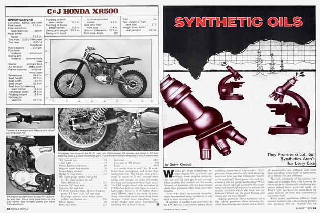
R.C. Engineering Pro Stock Suzuki Gs1000
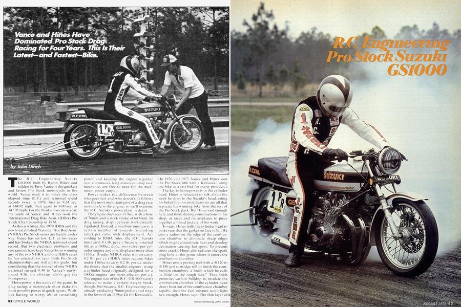
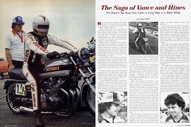
The R.C. Engineering Suzuki GS1000 built by Byron Hines and ridden by Terry Vance is the quickest and fastest Pro Stock motorcycle in the world. Vance used it to lower the class elapsed time (E.T.) and terminal speed records twice in 1978, first to 9.24 sec. at 144.92 mph. then again to 9.00 sec. at 147.05 mph. For the third consecutive year, the team of Vance and Hines won the International Drag Bike Assn. (IDBA) Pro Stock Championship in 1978.
As this is written, the 1979 IDBA and the newly-established National Hot Rod Assn. (NHRA) Pro Stock series are barely under way. Vance has set low E.T. at two races and has broken the NHRA terminal speed record. But two electrical problems and one rainout have kept Vance from winning any of the two NHRA and one IDBA races he has entered this year. Both Pro Stock championships are still up for grabs, but considering that the winner of one NHRA national turned 9.48 to Vance's earlyround 9.16. it's obvious who's got the horsepower.
Horsepower is the name of the game. In drag racing, a motorcycle must make the most possible power in quick spurts. Without having to worry about sustaining
power and keeping the engine together over continuous, long distances, drag race mechanics tire free to tune for the maximum power output.
Power makes the difference between who goes fast and who doesn't. It follows that the most important part of a drag race motorcycle is the engine, so we'll examine the R.C. Suzuki's powerplant in detail.
The engine displaces 1 176cc. w ith a bore of 76mm and a stock stroke of 64.8mm. In drag racing, displacement isn't directly regulated. Instead, a machine must carry a certain number of pounds (including rider) per cubic inch displacement. According to IDBA rules, the R.C. Suzuki must carry 8.1 lb. per c.i. because it started life as a lOOOcc. dohc. two-valves-per-cylinder engine and now displaces more than 1 165cc. (Under NHRA rules it must carry 8.2 lb. per c.i.) IDBA rules require bikes under 1 165ce to carry 8.2 lb. per c.i. under the theory that the smaller engines using a cylinder head originally designed for a lOOOcc engine are more efficient per c.i. The engine size of the R.C. G S 1000 w asn't selected to make a certain weight break, though, but because R.C. Engineering was already producing 76mm pistons and rings in the form of an 1 198ce kit for Kaw asakis.
(In 1976 and 1977. Vance and Hines won the Pro Stock title with a Kawasaki, using the bike as a test bed for many products.)
The key to horsepower is in the cylinder head. Hines is reluctant to talk about the work he does to the Suzuki's head, citing his belief that his modifications are all that separate his winning bike from the rest of the Pro Stock pack. But Hines said enough here and there during conversations in his shop, at races and on airplanes to piece together a broad picture of his work.
To start. Hines mills the cylinder head to make sure that the gasket surface is fiat. He cuts a radius on the edge of the combustion chamber to eliminate sharp edges which might concentrate heat and develop detonation-causing hot spots. To prevent stress cracks. Hines also radiuses the spark plug hole at the point where it enters the combustion chamber.
Hines uses a porting tool with a Ä 120 to # 180 grit cartridge roll to finish the combustion chambers, a finish which he calls "a little on the rough side." That finish promotes carbon buildup to insulate the combustion chamber. If the cylinder head draw s heat out of the combustion chamber rapidly, then the fuel mixture won't light fast enough. Hines says. The thin laver of carbon which develops after 10-15 runs prevents rapid heat loss and promotes faster combustion.
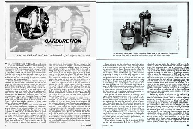
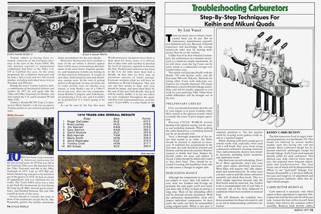
R.C. Engineering Pro Stock Suzuki GS1000
Similarly, Hines finishes the intake tract “on the rough side” to improve fuel atomization. As he explains it, because a drag motor doesn’t get as hot as other race engines, the fuel will not fully atomize if the intake tract is polished to a mirror finish. With his porting tool. Hines removes any casting imperfections and smooths out the intake tract. He also makes sure that the rubber intake hoses fit well at their junctions with the cylinder head and the carburetors, without turbulence-inducing steps or mis-matches.
The exhaust tract is smoother than either the intake or the combustion chamber, usually worked over with a # 280 to #320 grit cartridge roll. Hines uses his porting tool to remove any bumps or casting imperfections in the exhaust port so that the carbon buildup will be even. That carbon layer also serves to insulate the cylinder head from exhaust gasses. Any time heat is removed from the exhaust port (or upper end of the exhaust system), port velocity drops because energy that would otherwise be used pushing the gas out the port and through the exhaust pipe is dissipated into the cylinder head or airstream.
While enough to provide the insulating qualities that Hines wants, the carbon in the combustion chamber and exhaust port never reaches the excessive stage. According to Hines, the amount of carbon which develops during a season’s worth of quarter-mile runs is less than would build up if an average street rider took his stock GS 1000 back and forth to work for a week. Because the drag motor is always running at peak efficiency with maximum flow in the intake and exhaust ports, there isn’t a chance for excess carbon to build up.
It's very important, in Hines’ view, to give a new head a valve job after five or six runs. The intake valve seats move around a little in a brand new head, and if they aren’t attended to. the next time the engine won’t run as fast as it did at first. The valve seat will look fine, says Hines, but will be distorted just enough to allow a little leakage. Obviously, it's very important to have a positive seal.
The valves used in the R.C. Suzuki are both exotic and expensive. Made of titanium, the valves sell for $45 each but have several advantages over the standard alternative of stainless steel.
For example, the titanium valves weigh 40 percent less than stainless steel built to identical dimensions. Because the valves are lighter, valve control is better and the valve buckets stay on the cam lobes. W ith as much ramp speed (or valve acceleration rate) as the bike’s camshafts have, control is important to avoid valve float. Another benefit of light valves is that valve springs last longer than when steel valves are used.
Another advantage is that the titanium valves are more likely to return to their original shape after being nicked by a piston in the event of a missed shift or over-rev. Hines says that the valves “have a better memory,” and that titanium’s higher tensile strength allows the valve to bend farther and still come back to seat correctly.
However, titanium cannot withstand heat as well as stainless steel. For a long time, available titanium alloys couldn’t be used for exhaust valves because of the high temperatures encountered in exhaust ports. R.C. exhaust valves use one titanium alloy for the heads and another for the stems, the two pieces being welded together and bead blasted. The process was developed by NASCAR tuners less than a year ago. and at this writing R.C. Engineering is the only motorcycle aftermarket concern with access to such valves.
Intake valve size is 40mm, compared to 38mm stock, while exhaust valve size is the same as stock. 32mm. During installation the valves are backcut and the flat bottoms dished slightly. Hines makes sure that there is enough material between the face of the valve and the point at which the 45° angle starts. (Too little material could lead to premature leakage). Hines also checks the valves for any nicks or burrs, especially at the point where the stem radiuses into the head.
Valve stem diameter is stock 7mm. which Hines feels is actually a bit marginal considering the radical camshafts and the amount of spring pressure (90 to 95 lb. on the seat) run in the R.C. Suzuki. Because the valves are so much lighter than steel. Hines feels that any slight theoretical weight (or flow ) advantage gained by using undersized valve stems would not be worth the possible risk of the stems stretching and reducing valve clearance—which would then demand constant checking and adjustment. The bike is fitted with stock Suzuki valve guides.
Heavy-duty shot-peened siliconechrome valve springs are used with titanium collars. Racing valve buckets with lash adjustment shims underneath are used instead of stock-style buckets with shims on top. If the shims were on top of the buckets, they might be kicked out of place—and through the cylinder head—by the camshaft.
The camshafts are dual pattern, that is. the exhaust camshaft lobe profiles are different from the intake camshaft lobe profiles. The intake cam has 0.460 in. gross lift with 320° duration, w hile the exhaust camshaft has 0.405 in. gross lift with 328° duration. The exhaust camshaft profile is somewhat smoother to discourage exhaust valve float at very high rpm. Hines explains that in drag racing, valve float is inevitable, whether during the burnout or when the rider has trouble catching a gear or even misses a shift. If the intake valve floats, the piston is down (or going down) and so the valve isn't in danger of colliding wfith the piston dome. But the piston is approaching TDC when the exhaust valve is open so any float can result in hitting the piston and/or clipping the intake valve as well. To compensate for slightly less lift, (which also makes life easier for the exhaust valve springs) the exhaust camshaft has more duration.
The camshafts, which are sold as R.C. Engineering *520 cams, must be degreed in. To allow this, the camshaft sprocket bolt holes are slotted—when the cam sprocket bolts are loosened, the sprocket can be moved back and forth several degrees to allow precise camshaft timing. Measured at 0.050 in. lift, the recommended starting point for cam timing opens the intake valves at 21 ° BTDC and closes them at 65° AB DC; exhaust valves open at 70° BBDC and close at 20° ATDC.
Camshaft timing isn't as simple as setting the cams at the standard figures and forgetting them. Hines alters cam timing according to track conditions, and by doing so can move the powerband several hundred rpm up or down the scale. By closing the intake valves earlier, for example. cranking pressure can be altered. But according to Hines, many things—too many things to discuss here in detail —must be considered when playing with cam timing, including the type of cylinder head porting, the exhaust pipe, the carburetors, riding style, gearing, ignition timing, and jetting.
The cam is driven off the crank via an R.C. Engineering cam chain, which has looser tolerances than the stock chain to avoid pin seizure or anv tendency to not precisely follow the small crankshaft sprocket at very high rpm.
Hines modified the top of the cylinder head to accept an idler roller from a GS750, mounted between the intake and exhaust cams. The idler is necessary to control cam chain w hip and maintain precise camshaft timing.
In early dyno tests prior to the 1978 season—when Vance and Hines switched from Kawasaki to Suzuki —Hines had problems w ith the cylinder head lifting off the cylinders—and spraying gas and oil out the sides—and the base gasket being beaten to pieces between the cylinder and the crankcases. The cure came in three parts. First, an R.C. copper alloy head gasket—similar to the ones already developed for Kawasakis and Hondas —was made and installed. Second, a small groove 0.035 in. deep was milled around the top of each nickel-alloy cylinder liner to hold an 0.047 in. o.d. copper w ire. Third. R.C. heavy-duty 4130 chrome moly steel cylinder studs were installed. The R.C. studs have cold-rolled threads on each end and have a shank diameter of 3/8 in., compared to the stock mild steel stud's shank diameter of 5/16 in.
The combination of those three measures keeps the compression inside the cylinders and prevents cylinder and cylinder head movement. Still using the stock Suzuki base gaskets. Hines has not had anv further problems with leakage or gasket pulverization.
Hines swears by forged pistons for several reasons. According to Hines, forged pistons are dimensionallv much stronger than cast pistons because the metal is more dense. In the earlv days of piston forging, the increased density of the metal caused problems with excess heat expansion and the transfer of too much heat to the wrist pin. But current technology allows the use of a verv high-silicon content in the piston allow controlling expansion and heat transfer and improving lubricity. A properlv-designed forged piston can be installed with piston-to-cvlinder wall clearances as small as those used in the case of the best cast pistons, while delivering more strength. In addition, during the forging process the alloy tends to develop a grain flow in the area of wrist pin bosses, increasing strength in this critical area. Hines says that forged piston ring lands are significantlv better able to withstand detonation and other combustion abnormalities than are cast pistons.
But the pistons that Hines installs in the R.C. Suzuki Pro Stocker are neither ordinäre nor off the shelf. He starts w ith a 4032 high silicone alloy forged piston blank with the second and oil control ring grooves cut. but without the top ring groove.
The first step is to shape the piston dome to fill the combustion chamber enough to vield a 13.5:1 c.r. without bending the valves or hitting the spark plug. Each valve pocket is raised in the middle to follow the dished contour of the valve bottoms, a feature which helps purge unburned exhaust gasses at TDC on overlap (both valves open). The raised bumps in the valve reliefs clean out the space underneath the valves to make more room for new fuel/air mixture. A notch cut in one side of the raised dome allows clearance for the spark plug electrode.
That's fairly standard stuff. Hines gets exotic when it comes to rings. He cuts his own top compression ring land because production tolerances of 0.0015 to 0.0020 in. are too great to work with gas ports (more on that later). The top land is located as close to the top of the piston as is possible (about 0.10 in.) because Hines has found in dyno tests that pistons with high rings make more power than do pistons with relatively low top rings.
Hines cuts the ring land about 0.001 in. smaller than the thickness of the top compression ring, then laps in the ring using a special fixture he designed and built to a finished up-and-down tolerance of less than 0.0005 in. with zero back clearance.
The special fixture holds the ring and loads it as if it were in the cylinder bore. Besides making the close tolerances possible. lapping the ring also ensures that the ring itself is perfectly flat on both sides, with no bevel or irregularities. The lapped finish provides a good seal.
A good seal is essential because Hines uses eight evenly-spaced. 0.045 in. diameter "gas ports” leading from the edge of the piston top to the top of the upper ring land, at an angle.
Combustion pressure through the gas ports forces the upper ring out against the cylinder w all. The result is an excellent seal with little blow bv. Almost all the combustion pressure is utilized in the production of horsepower. In leakdown tests, the R.C. Suzuki typically loses less than one percent of pressure over a given time period tested cold. (A typical stock street bike will lose six to 10 percent pressure in the same test).
The top compression ring itself is tool steel. 0.031 in. thick with 0.125 in. radial thickness. Tool steel is heat resistant, can withstand detonation without cracking or breaking, and has excellent wear characteristics.
The middle ring is a cast iron taper-face scraper ring run at 0.0015 in. top-to-bot-> tom clearance. This second ring is located 0.30 in. below the top ring. Plenty of piston metal backs up the upper compression ring and holds it in precise position.
The third ring is a standard R.C. threepiece oil-control ring.
An annular groove cut between the second ring and the oil control ring removes oil on downstrokes, and channels it to holes leading to the wrist pin. The pressure between the second ring and the oil control ring is greater than crankcase pressure, so this system in essence force feeds oil to the wrist pin.
Oil scraped off the cylinder wall by the oil control ring is fed via channels to drain holes leading into the center of the piston. The drain holes themselves are notched to encourage oil to run down the piston skirt.
Three 3/8-in. chamfered holes drilled in the piston skirt on both the intake and exhaust sides serve two functions: to lighten the piston without reducing strength and to provide extra skirt oiling. The piston never gets hot enough to fully expand into a true cylindrical shape, thus the skirts are heavily loaded and need additional oiling to prevent seizures.
However. Hines points out that drilling such piston holes isn’t something for the home tuner to attempt; the modification— if not done correctly—can cause the piston to crack and explode. Hole spacing must be even and precise, and the edges chamfered and deburred to avoid concentrating stress and to prevent cracking.
Grooves between the piston skirt holes serve as oil reservoirs, holding lubricant on the skirt faces.
The pistons are run with 0.050 to 0.055 in. clearance between crown and cylinder head combustion chamber.
The result of all the effort and work is pistons that don’t normally require any attention during a Pro Stock season. Once Hines has machined the pistons, the weight is down to 235 to 240 grams without wrist pin and rings, compared to the starting weight of 300 grams for the blank.
Wrist pins are R.C. hard chromed with a taper bore, with greater wall thickness (and strength) in the middle where the pin meets the connecting rod. The pins weigh less than a straight-bore pin of comparable strength.
Teflon retainer buttons position the pins, the buttons riding directly on the cylinder walls. (Because the Teflon buttons wear into egg-shapes after a certain amount of use, Hines recommends tapered aluminum buttons for street and road racing use.)
When Hines assembles his racing engines. he oils the pistons and rings first. According to Hines, if the engine is assembled with the pistons and rings dry. the first few strokes upon start-up produce excessive wear. (Some racing machines may have to be assembled dry if the rings used are uneven, with low spots in their circumference.)
The R.C. Suzuki is fitted with Amal carburetors for several reasons. Foremost, the carburetors are readily available and are narrow enough to fit in the available space. An alternative to the Amals would be 31mm Keihin CR carbs. but CRs are available only through limited sources. CR carburetors also have a push-pull linkage which hits on the Suzuki cylinder head unless spacing blocks are used.
Amals have another advantage in that carburetor size may be easily varied—the same basic body casting is used for production-line Amal 32mm, 34mm and 36mm carbs. Hines takes standard 34mm Amals and bores them out to 35mm to clean up what he describes as cobby, rough bores.
The carbs are bolted to a piece of aluminum strap, producing a single unit, or bank. But the mounting surface must be machined flat before each carburetor is bolted up. As it comes cast from the Amal factory, the surface is uneven and rough. If the carbs are bolted together with the mounting surface un-machined. tightening the mount bolts will distort the slide bore and cause the slide to stick open, the problem surfacing in one out of every four curbs on the average.
Hines jets to suit each individual engine he builds but begins with = 260 to =270 main jets, installs =3.5 slides (3.0 slides are stock) and fills each slide with lead so it won't float on the airstream and produce an erratic idle or return to idle slowly w hen blipped in the staging area.
“Believe it or not." says Hines of that particular modification, “that's just to make the bike sound better, make it sound like a motorcycle in the staging area." Hines, the man so dedicated to function, has a bit of showman in him after all.
Hines makes sure that the distance from the needle jet to the top of the fuel mixture bleed tube is equal length on all four curbs, and taps any errant bleed tube up or down with a brass punch to get it w here he wants it. If the distances are uneven, one cylinder may run lean or rich at partial throttle and the bike will hesitate slightly and run on three cvlinders off the line.
Hines removes the enrichening circuit in each curb because he had problems with the plungers re-seating. The bike is push started because the electric starter is removed and the sidecase hole filled with an R.C. plug to save weight. Before starting. Hines squirts each curb throat w ith raw gas from a small oil pump can.
Velocity stack length was determined by research on the dyno. Hines starts with stock Amal stacks and shortens and flares them on a lathe. The stacks on cylinders one and four are 1.5 in. long while the stacks for cylinders two and three are 2.0 in. long to equalize intake tract lengths. (In the stock Suzuki cylinder head casting, the inside and outside cvlinder intake tracts vary in length, to expedite mounting the four curbs as inboard as possible in an effort to maximize rider knee room.)
Final jetting is always done at the track. Hines explains that on the dyno. jetting is less critical in determining horsepower output than it is at the racetrack. In addition. Hines doesn’t run the engine to maximum rpm on the dvno. instead limiting testing rpm to about 10.000. (He admits that he once ran a Kawasaki Pro Stock motor up to 12.000 rpm on the dyno. and that it made about 40 horsepower less than it did at 10.000 rpm). At the racetrack, the motorcycle is typicallv turned to 1 1.000 or 1 1.500 rpm. and is shifted bv sound. Hines savs no tach could keep up w ith the acceleration of his drag motor.
Two '/4-in. inside diameter fuel lines feed from individual petcocks located on each side of the 4 gal. fiberglass fuel tank. Two petcocks are used because the tank has a high backbone, and Hines can vary wet weight by altering the amount of gas carried in the tank—with two lines, he doesn't have to worry about gas being isolated in one side of the tank. A balance tube between the two main fuel feed lines compensates in case one side of the tank contains more fuel than the other. (Once two cylinders on the bike cut out w hen one side of the tank went dry mid-run. Hines doesn't like to take chances w ith repeating mistakes.)
The bike runs on 127-octane H&H Blue racing gasoline, which costs $2.50 per gallon.
The throttle cable is a stock one-intofour early-model Honda CB750 part.
The exhaust system is mandrel bent but hand assembled to allow clearance for the lead ballast weights attached to the front bottom of the frame. Head pipes are 1.5 in. o.d. and are 26 in. long, leading into a 2.5in. collector, which in turn leads into a standard R.C. Engineering megaphone. To streamline flow, at the center of the junction of the four head pipes. Hines installs a 3/4-in. o.d. bullet-shaped piece of steel rod called a “goilet". The system is routed underneath the center of the engine so that if the bike gets out of control at speed it won’t drag the pipe on one side or another.
The bottom of the collector is actually flattened from hitting bumps, but Hines says that horsepower readings on the dyno haven’t been affected, and that he is reluctant to change a pipe that works just because it’s flat on the bottom.
Ignition is by a total-loss, battery powered Martek CDI with Hall effect magnetic pickups, which Hines says fires the ignition at the same point (measured in crankshaft degrees) at 0 rpm and at 12.000 rpm. The stock Suzuki ignition advance unit is welded at the full advance of 40° BTDC, but Hines leaves the advance weights on and reinforces the arm stops, arm pivot pins and spring pins with weld. Aluminum shims used underneath the advafice mount bolt lock the assembly down and remove any trace of slop. Hines uses the modified stock advance unit—instead of building a one-off part—so that in case of failure a replacement is as close as the nearest stock Suzuki part and the welding equipment carried in the R.C. truck.
Connecting rods are stock, but Hines welds the pressed-together crankshaft at the pins and the drive sprocket to prevent slippage at high rpm. Although admittedly crude, welding is an effective method of maintaining crankshaft alignment under the extreme loads encountered in a ProStock engine. Crankshaft balance is not affected, says Hines, as long as an equal amount of weld bead is used on the pins, which are on opposite sides on the crankshaft centerline. Weld on the main bearing pin doesn’t affect crankshaft balance because it’s so close to the centerline of the rotating mass, as opposed to being out on the periphery. In actual tests using a perfectly-balanced Honda crankshaft, Hines welded a certain amount of bead on one crank cheek and an equal amount on the opposite cheek, reinstalled the crankshaft in the balancer, and couldn’t detect a difference in balance.
Hines polishes the center crank pin and radiuses the 90° angle where the pin rises into the camchain sprocket and the center main bearing shoulders—the standard angle (which isn’t a problem on stock machines) concentrates stress that could lead to crankshaft breakage under racing conditions.
Hines also polishes the leading edge of each crank throw in an effort to reduce friction as the crankshaft plows through the oil in the crankcases, and installs a crank wiper to remove and break up oil rotating with the crankshaft. The wiper is made cf aluminum strap 1 /8-in. thick and 1.0 in. wide, and is heli-arced into the bottom crankcase half. How much force (and potential power loss) is involved in oil moving with the crank is best illustrated by the following fact: the oil hits the crank wiper hard enough to, in one instance, fracture the heli-arc welding at one end of the installation.
Hines builds a rear sump pickup for the oil pump out of aluminum plate and pipe, and cuts out sump baffle plates so that under acceleration, oil will instantly run across the bottom of the sump pan and back to the pickup. It is essential—especially considering the radical valve train run in the Pro Stocker—that the top end always has adequate lubrication. If the stock oil pickup location were retained the oil would run to the rear of the pan, away from the pickup, during runs.
To further ensure that the cams receive enough oil, Hines installs a flow restrictor into the transmission oil feed orifice on the output side of the oil pump. The restrictor cuts down flow to the transmission and diverts it to the top end. Hines found that the engine didn’t have adequate oil pressure to the top end at low rpm before the modifications, and says that after the change the transmission still gets plenty of oil to go a quarter mile.
Fiber clutch plates are standard 1979 GS1000 parts, with Barnett copper-coated steel plates. Standard steel plates are dimpled by the spanking die used to straighten them after they are stamped out. The dimpling holds oil which may contribute to slip. Barnett plates are ground after stamping and so are smooth. The copper coating transfers heat and hot spots don't develop at any one point on the plate.
Transmission parts are micro-plated, a form of hard chrome calculated to reduce drag. Gears are undercut for positive engagement and the pressed-on second gear is welded in place to prevent movement. The Vance and Hines Suzuki uses the first four gears in a run down the strip, while competitors on Kawasakis use five gears. Suitable close-ratio aftermarket gearsets aren’t yet available for Suzukis.
If Hines runs a stock five-speed with appropriate countershaft and rear wheel sprockets to run through the lights at peak rpm in fifth gear, then first gear is ultra low. which makes getting off the line without smoking the rear tire more difficult. There is a road racing close-ratio aftermarket transmission available, but Hines explains that the first gear is too tall for drag racing applications.
Once he leaves the line in first gear. Vance never again touches the clutch lever. Instead, he keeps the throttle wide open and pushes a small handlebar-mounted button with his left thumb. The button activates a Murdoch air shifter—air pressure from a tank made of plastic pipe is released and enters a slave cylinder located under the countershaft cover. The slave cylinder pushes on a bracket welded onto the shift shaft, rotating the shaft forward. Inside the cases, as the shift drum rotates,, the star wheel on one end of the drum depresses another switch button w'hich instantaneously kills the engine. Only the points of the star wheel can contact the internal kill button, so as the star rotates and the particular point within range passes over the button, the button returns to its normal position and the ignition circuit is again complete.
Final drive gearing is usually 17/46. with #50 Tsubaki chain and several master links used to facilitate gearing changes. Hines settled on #50 chain because he wants the lighest chain he can use without risking a failure.
The frame is modified Suzuki, with rake increased to 33° for maximum straightline stability. The frame is placed in a jig, and the top frame tube cut. pulled back and welded, with extra triangulation added. The rectangular, cross-braced swingarm is made by Kosman from 4130 chrome moly. and measures 1.5 in. x 1.0 in. in cross section. The addition of the 24.5in. long (measured from pivot to axle centerpoints) swingarm combines with the 33° rake to give the bike a wheelbase of 68 in., the maximum allowed by IDBA rules. An extra load arm bolts up outside the frame pivot on the countershaft sprocket side and prevents swingarm misalignment or movement caused by engine torque during acceleration. (Without an extra load arm. the bike would veer to one side as it left the line.) A 2.5-in. long, '/2-in. preload bolt mounts on top of the swingarm pivot tube and backs up against the engine cases so that the engine mounts are not excessively loaded during a run. Without the bolt in place, the top rear motor mounts break and chain adjustment cannot be accurately set or maintained. An early-model Honda CB750 batterv box is rubber mounted to the forward section of the swingarm, keeping the weight of the battery low. The 18-in. Kosman front wheel has a magnesium hub and WM1 Akront rim. with 10-gauge spokes, and is fitted with a Goodyear D 1390 3.25-18 road racing slick. The rear wheel is also from Kosman with a magnesium hub. 18-in. WM6 DID rim, 8gauge spokes and a Goodyear D 138 1 3.5018 road racing slick. Hines solved a problem with the sprocket mount bolts pulling out of the rear hub by installing heli-coil thread inserts. Hines drilled and tapped holes in the rim. ground points onto 10 'A20 alien-head screws and installed the screws to hold the bead and keep the tire from spinning on the rim. Rear tires last 10-12 runs.
Vance and Hines experimented with wider rear rims and tires two years ago. but encountered several problems. The center of the super-wide tires caved in as the bike launched off the line. The sidewalls weren't heavy enough to support the center of the tread surface. Hines considered placing a stiffener of some sort inside the tire to improve contact, but abandoned the idea. Any potential difference in traction, he reasoned, wouldn't be worth the disadvantage of the extra weight of the larger wheel and tire, especially because the tire mass must be accelerated so drastically during a run. Now. super wide wheels and tires are appearing on pro-stockers again, but Vance and Hines retain their present combination. and still have the fastest and quickest machine. Ceriani forks are fitted with spring preload spacers to limit travel to 2.0 in., which makes the forks very stiff. Hines doesn’t want the bike to dive forward as it comes off the line, which tends to be a problem with softly-sprung, long-travel forks on a drag bike. The stiffer fork springing keeps the bike level at launch, and the front wheel lifts as the bike slams the wheelie bar down. In conjunction with the wheelie bars, struts 1034 in. long and made of34-in. 4130 tubing replace the rear shocks. Under Pro Stock weight-break rules, the minimum ready-to-race w eight of the R.C. Suzuki is 587 lb. Vance weighs 165 lb., the bike—with 1 gal. of gasoline—395 lb. To make the weight minimum. Hines bolts 27 lb. of lead weights to the frame just ahead of the crankcases. Hines is constantly experimenting, trying different crankshaft modifications, building a dry sump system, looking for an improvement that might yield just a little quicker E.T. But once he has an engine that runs as he thinks it should, he builds another and works on it until it's faster than the engine then being used. Then Hines swaps engines, saves the first one for a spare, and begins building another. That way, if anything breaks he always has a good spare engine ready, yet doesn't risk a known combination while experimenting.
The dual piston front brake caliper is made by Grimeca. as is the master cylinder. The rear master cylinder is stock Suzuki, the caliper Grimeca. Both front and rear discs are drilled cast iron from Kosman. The seat pan is fiberglass and the side panels of the stock seat have been replaced by leather. The standard vinyl upholstery tears from the force of acceleration working against rider weight, and the leather replacement doesn't. The top of the seat remains standard vinyl. The stock headlight shell is retained, but the wiring and headlight assembly are removed and replaced by a plastic cover painted to resemble a headlight lens. Chassis weight distribution and wheelie bars are critical. The goal is to get weight transfer to the rear tire, not the wheelie bar. The ideal drag bike. Hines says, would not have or need a wheelie bar because any force applied to the back of the bars must be subtracted from rear wheel traction, but with wheelbase limited by IDBA rules, the wheelie bar is necessary to keep the bike generally on the ground and to make it rideable.
The bars now mounted on the R.C. Suzuki are 42 in. long, a length reached after experiments with shorter bars. Hines says that he wants as much weight as far forward and w heelie bars as long as possible. He isn't satisfied with the bars he has now. and plans to keep trying different combinations. Limiting factors on w heelie bar length include flex and design. A certain amount of flex is needed for loading, but not to the point where the bars bend or fold up.
continned on page 97
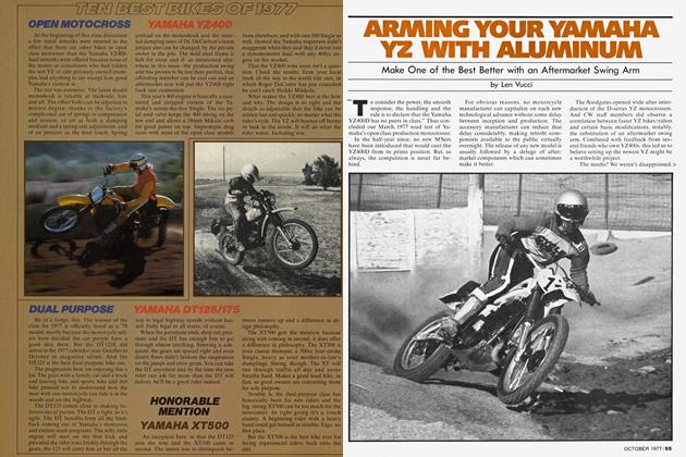
Pro Slock SuzukiGS1000
$15,000
continued from page 63
On the R.C. Engineering dyno. the engine currentlv in the bike produces a sustained 175 uncorrected horsepower at 11.000 rpm and 98 ft. lb. of torque at 8000. But Hines is quick to point out that dynos don't agree, and usually won't show the same output figure for the same engine under the same conditions. Hines uses his dyno for .relative horsepower measurement. He runs a known engine combination on the dyno. notes the figures, puts a new' combination on the dyno. and thus learns whether he’s going backward or forward in terms of peak power and powerhand. According to his dyno. he built 20 more horsepower into his Suzuki’s engine over the course of the 1978 season.
Hines says a good engine will last a season if properly maintained, while a cylinder head will last indefinitely, barring mishap. What must be frustrating for Hines is the fact that Vance has lost two races this season due to fluke malfunctions of auxiliary components.
Mounted on the Suzuki’s handlebars is an ordinary household electrical extension cord outlet. When Vance gets on the hike, he inserts a household electrical plug, which is connected at the other end to his leathers via an alligator clip. The plug completes the ignition circuit, and if Vance fell off the bike, the plug would be pulled out of the socket and the ignition turned off. At one race this year, the plug somehow came out of the socket on the starting line. Vance was out of luck and out of precious Pro Stock points.
At another race, there was a last minute delay at the starting line just before Vance and Hines fired up their bike. The ignition was on. and Hines had just squirted raw gas into the carburetor velocity stacks to aid starting. Because he didn't want to risk running down the total-loss battery during the wait. Hines pulled the plug to turn ofif the ignition. When the circuit broke, the CDI fired one spark plug, even though the intake valve was open. The resulting misfire bent that cylinder’s carburetor’s slide enough that the slide wouldn’t move, and Vance was out again. At that race, the winner ran 9.48. Vance had turned 9.16 in an earlier round.
Elukes or no flukes, no matter who wins, you can believe this: The Vance and Hines Suzuki is the quickest, fastest Pro Stock drag race motorcycle in the w'orld. EE