The Cannon Connection
The cannon connection
TDC
Kevin Cameron
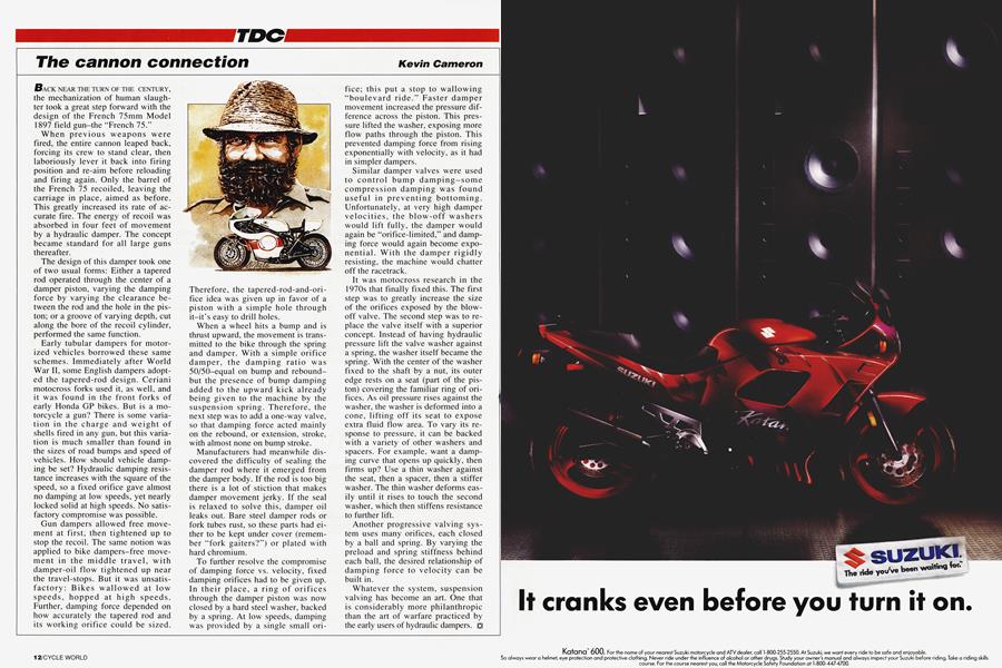
BACK NEAR THE TURN OF THE CENTURY, the mechanization of human slaughter took a great step forward with the design of the French 75mm Model 1897 field gun-the “French 75.“
When previous weapons were fired, the entire cannon leaped back, forcing its crew to stand clear, then laboriously lever it back into firing position and re-aim before reloading and firing again. Only the barrel of the French 75 recoiled, leaving the carriage in place, aimed as before. This greatly increased its rate of accurate fire. The energy of recoil was absorbed in four feet of movement by a hydraulic damper. The concept became standard for all large guns thereafter.
The design of this damper took one of two usual forms: Either a tapered rod operated through the center of a damper piston, varying the damping force by varying the clearance between the rod and the hole in the piston; or a groove of varying depth, cut along the bore of the recoil cylinder, performed the same function.
Early tubular dampers for motorized vehicles borrowed these same schemes. Immediately after World War II, some English dampers adopted the tapered-rod design. Ceriani motocross forks used it, as well, and it was found in the front forks of early Honda GP bikes. But is a motorcycle a gun? There is some variation in the charge and weight of shells fired in any gun, but this variation is much smaller than found in the sizes of road bumps and speed of vehicles. How should vehicle damping be set? Hydraulic damping resistance increases with the square of the speed, so a fixed orifice gave almost no damping at low speeds, yet nearly locked solid at high speeds. No satisfactory compromise was possible.
Gun dampers allowed free movement at first; then tightened up to stop the recoil. The same notion was applied to bike dampers-free movement in the middle travel, with damper-oil flow tightened up near the travel-stops. But it was unsatisfactory: Bikes wallowed at low speeds, hopped at high speeds. Further, damping force depended on how accurately the tapered rod and its working orifice could be sized.
Therefore, the tapered-rod-and-orifice idea was given up in favor of a piston with a simple hole through it—it’s easy to drill holes.
When a wheel hits a bump and is thrust upward, the movement is transmitted to the bike through the spring and damper. With a simple orifice damper, the damping ratio was 50/50-equal on bump and reboundbut the presence of bump damping added to the upward kick already being given to the machine by the suspension spring. Therefore, the next step was to add a one-way valve, so that damping force acted mainly on the rebound, or extension, stroke, with almost none on bump stroke.
Manufacturers had meanwhile discovered the difficulty of sealing the damper rod where it emerged from the damper body. If the rod is too big there is a lot of stiction that makes damper movement jerky. If the seal is relaxed to solve this, damper oil leaks out. Bare steel damper rods or fork tubes rust, so these parts had either to be kept under cover (remember “fork gaiters?”) or plated with hard chromium.
To further resolve the compromise of damping force vs. velocity, fixed damping orifices had to be given up. In their place, a ring of orifices through the damper piston was now closed by a hard steel washer, backed by a spring. At low speeds, damping was provided by a single small ori-
fice; this put a stop to wallowing “boulevard ride.” Faster damper movement increased the pressure difference across the piston. This pressure lifted the washer, exposing more flow paths through the piston. This prevented damping force from rising exponentially with velocity, as it had in simpler dampers.
Similar damper valves were used to control bump damping-some compression damping was found useful in preventing bottoming. Unfortunately, at very high damper velocities, the blow-off washers would lift fully, the damper would again be “orifice-limited,” and damping force would again become exponential. With the damper rigidly resisting, the machine would chatter off the racetrack.
It was motocross research in the 1970s that finally fixed this. The first step was to greatly increase the size of the orifices exposed by the blowoff valve. The second step was to replace the valve itself with a superior concept. Instead of having hydraulic pressure lift the valve washer against a spring, the washer itself became the spring. With the center of the washer fixed to the shaft by a nut, its outer edge rests on a seat (part of the piston) covering the familiar ring of orifices. As oil pressure rises against the washer, the washer is deformed into a cone, lifting off its seat to expose extra fluid flow area. To vary its response to pressure, it can be backed with a variety of other washers and spacers. For example, want a damping curve that opens up quickly, then firms up? Use a thin washer against the seat, then a spacer, then a stiffer washer. The thin washer deforms easily until it rises to touch the second washer, which then stiffens resistance to further lift.
Another progressive valving system uses many orifices, each closed by a ball and spring. By varying the preload and spring stiffness behind each ball, the desired relationship of damping force to velocity can be built in.
Whatever the system, suspension valving has become an art. One that is considerably more philanthropic than the art of warfare practiced by the early users of hydraulic dampers.