Easy Fork Fixes You Can Do At Home
Easy Fork Fixes You Can Do At Home
This month: Yamaha's 350 and 650; Kawasaki's 400, 750 and 900.
BOB ATKINSON
Suspension modifications are generally not considered by street riders, which is understandable for a couple of reasons. In the first place, street surfaces are fairly smooth, so most riders ignore suspension in their quest for comfort. Instead, they concentrate on accessory seats, handgrips and the like. And secondly, kits to improve suspension on road bikes are either not available or are too new to have gained public acceptance.
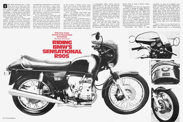
If you are a believer in the smooth street theory, you are wrong, and considering BMW’s approach will prove it. BMWs have two to three more inches of travel in the forks than is common among Japanese bikes. They also use a relatively soft spring, preloaded to hold the bike up, as opposed to a heavier spring without much preload. What they have gained is a plush ride with good stability on rough roads. This plush ride and its resulting rider comfort have made BMW legendary worldwide.
Lending even more strength to the soft suspension theory is Yamaha. For 1976, they have drastically altered their production roadsters. In place of heavy springs are soft ones with considerable preload. There’s even been a marginal increase in travel.
We are really glad to see this, but it doesn’t do much for owners of earlier Yamahas or other Japanese machines. For them, modification is the answer.
This installment deals with some mediumand large-displacement Yamahas and Kawasakis. Next month, CYCLE WORLD will show you how to fix some popular Hondas and Suzukis.
CYCLE WORLD'S TESTING PROCEDURE
Before any modifications were begun, all of the machines chosen were ridden and evaluated for both handling and comfort. Next, each machine was taken to Number One Products and disassembled. HD-315 oil was substituted for stock in the forks. Both the forks and shocks were then dyno tested (Continued on page 102) to determine compression and rebound damping. Springs were evaluated on a separate spring tester.
Continued from page 43
After the initial dyno runs, the forks were disassembled to analyze their construction and determine whether they had enough engagement for extension. Engagement is the number of inches that the stanchion tube and slider overlap when the fork is at full extension. If the fork involved had less than four inches of engagement stock, it was not extended.
We then discussed handling, ride characteristics and machine weight. With this information in mind, Brian Fabre decided on spring rates appropriate for the weight of each machine, then began altering damping rods (or making new ones in some cases) in an effort to match compression and rebound damping characteristics to the spring. Forks were extended to allow more travel wherever possible.
Finally, the bikes were reassembled and reevaluated for ride and handling.
INTERPRETING THE CHARTS AND DRAWINGS
Reading dyno charts is not difficult, but an explanation is necessary. The horizontal line extending across the chart labeled 0 represents the point at which the suspension component changes direction. The portion above the 0 line represents pounds of compression damping. The portion below the 0 line represents pounds of rebound damping. The number of pounds the remaining horizontal lines on the chart represent can vary to suit the component being tested.
Ideally, a fork should have 6 to 1 2 pounds of compression damping, depending on machine weight and spring rate. Rebound damping should be approximately 1 5 percent higher than the preloaded spring rate. Rebound damping needs to be higher than compression damping because of the effects of the spring.
Road bike shocks in a conventional position should have 10 to 20 pounds of compression damping depending on machine weight and spring rate. More compression damping is necessary here because the rear suspension takes more load. Again, rebound should be approximately 15 percent of the preloaded spring rate.
The horizontal scale represents .25 in. per division; from this you can tell how far the suspension component is being stroked on the dyno. In the charts that follow, .25 in./div. x 6 divisions (the width of the graph) equals 1.5 in. That means the suspension component is being moved 1.5 in. up (the height of the graph above the 0) and 1.5 in. down (the height of the graph below the 0), for a total of 3 in.
Frequency is always 2 Hz or 2 cycles per second. This is a test standard. One cycle can be described as moving the suspension component from 0 or rest, to 1.5 in. of compression, back through 0 to 1.5 in. of rebound, then back to 0 or rest.
The drawings represent damper rods that control the rates of compression and rebound damping. Altering the diameter of the compression or rebound holes is the method used to alter damping rate. The stock damper rod is represented on the left. The individual components that make up the complete rod are labeled. The modified rod is represented on the right. The actual alterations are described on this drawing to eliminate any confusion when you modify your own bike.
DAMPER ROD REMOVAL AND REINSTALLATION
Before the damper rods can be modified and/or the forks extended, the rods must be removed from both fork legs. The best way to accomplish this is as follows: Place the machine on the centerstand and weight the rear until the front wheel comes off the ground. Remove the axle, front wheel, fender, and any brake linkage. With the forks still bolted in the triple clamps, remove the Allen bolts in the bottom of the fork slider. This is located directly above the axle on most machines. With the bolt removed, let the oil drain, then pull down on the slider to remove it from the stanchion tube. Next, loosen the triple-clamp pinch bolts and slide the stanchion tubes downward to remove the upper fork assembly from the motorcycle. Remove the fork cap. Slide out the spring and any spacers. Turn the stanchion tube over and the damper rod should slide out. If it doesn’t, you’ll have to remove a circlip (present on some models) from the bottom of the damper rod.
Reassembly after modification is just the opposite. The only tricky part is getting the Allen bolt tight on the bottom of the slider. To accomplish this, it will be necessary to install the fork spring and cap. This keeps the damper rod from turning while the Allen bolt is tightened. Once tight, remove the cap and spring. Add oil until the rod is just covered. With the rod covered with oil, move the slider up and down. If the oil level drops, repeat the procedure until the oil level remains constant and just covers the top of the rod. Reinstall the spring, cap, wheel, etc., and you’re on your way.