Troubleshooting Ignitions: Capacitor Discharge Systems
TROUBLESHOOTING IGNITIONS: CAPACITOR DISCHARGE SYSTEMS
Tuning CD Ignitions Requires Special Equipment and Special Care
Len Vucci
This article pertains only to theory and adjustment of CD ignitions. While it contains detailed instructions for some models, these models are included here for illustration only.
For troubleshooting tips, detailed tuning information, specifications, etc., for the make or model you own, consult your owner’ s or shop manual.— Ed.
THIS THIRD installment of our ignition tuning series is a guide to proper maintenance of capacitor discharge ignitions.
CD ignitions are relatively new and still have an air of mystery about them. This can be a handicap for the tuner/owner, because we tend to shy away from working on components we don’t understand.
Not to worry. CD ignition isn’t difficult. It isn’t all that different from conventional ignition, in fact.
For both reasons, we’ll begin this explanation of CD procedures with a brief review of the fundamentals as they apply to all types of motorcycle ignition systems.
In simplest terms, the object of all ignition systems is to produce a powerful spark and deliver it to the right place at the right time.
When applied to a spark plug, the resulting spark ignites the fuel mixture. This high voltage must be sufficient in amplitude, and occur precisely at the right time. If either of these conditions is not satisfied, a loss of performance and/or reliability will be experienced. A gross malfunction might render the motor inoperable, sometimes causing severe damage. (Holed pistons do make dandy paperweights, though).
WARNING
CD ignitions are so powerful that they can damage themselves under some circumstances.
One such circumstance is when the engine refuses to start and the owner checks for spark. Fine. But if the engine is cranked with the spark plug removed, so that the spark (if any) can be seen, be sure to ground the plug. If that hot spark has nowhere else to go, it will zap back into the system with serious consequences.
The same warning applies to any engine testing involving the use of the ignition system when the plugs are removed. Ditto for clearing a flooded engine by removing the plugs and cranking, kicking or pushing the engine so it revolves and dries the cylinders.
In short, when a CD ignition is making sparks, be sure the sparks have somewhere to go.
Assuming that the individual components of an ignition system are operational, our main concern is their proper adjustment.
BATTERY/POINTS IGNITION
When a battery is used for ignition purposes (some bikes use the battery for lighting and accessories), its normal six or 12 volts must be increased tremendously. Requiring approximately 15,000 volts to fire properly, the spark plug is supplied by a step-up transformer, called an ignition coil. The battery voltage is applied to one side of this coil through a set of contact (breaker) points. When the points are opened by engine rotation, the coil steps up the six or 12 volts to the required sparking voltage, firing the plug.
TIMING ADJUSTMENT
Procedures for adjusting the timing of a battery/points ignition system are relatively painless and essentially the same regardless of manufacturer. The points gap is set to specifications (usually .015-.020 in.) after rotating the engine so that the points are at maximum opening. This step is repeated as necessary for multi-cylinder engines.
Since the ignition spark occurs at the instant the points separate, a suitable device is needed to monitor point opening. This may be a simple test light, a buzzer or other audible device, a VOM (Volt-Ohm Meter), or a power timing light. With one of these instruments, the contact points are adjusted to open at the proper time. (Determining the correct firing point will be elaborated upon subsequently). For multi-cylinder engines, the set of points mounted directly to the main (largest) breaker plate is adjusted first. The remaining set(s) of points, mounted on a smaller movable breaker plate, can then be timed.
MAGNETO/POINTS IGNITION
Magneto/points ignition makes use of a simple electro-magnetic principle. No battery is needed. Whenever a magnetic field crosses a conductor (i.e., a wire), an electric current is produced.
For motorcycle engine applications, a strong permanent magnet is embedded in the flywheel. As the flywheel rotates, it induces an electric current into an adjacently mounted coil. The magneto coil produces several hundred volts, which is applied to the ignition coil. The coil steps up this voltage to the level needed to fire the plug.
lo accurately control the spark timing, a set of contact points is employed. Acting in much the same manner as in battery-type ignition systems, spark occurs as the points open. Utilizing an appropriate monitoring device, the contact points are adjusted to open at the proper time.
In some Singles, there is merely a point gap adjustment, and no separate timing adjustment. Proper timing is obtained by varying the point gap. Decreasing gap retards ignition; increasing gap advances ignition.
CAPACITOR DISCHARGE IGNITION
By eliminating wear-prone mechanical breaker points, CDI rarely if ever requires adjustment. Additionally, a hotter, more consistent spark is available, increasing performance and reliability.
A (primary) voltage is derived from either a magneto assembly or a battery with some additional circuitry. These several hundred volts will be stepped up by the ignition coil to produce a spark at the plug.
Its method of controlling firing point is CDI’s big advantage. A rotating magnet and pickup coil produce a small but regular pulse of electric current. The occurrence of this pulse, analogous to contact breaker opening, determines firing point.
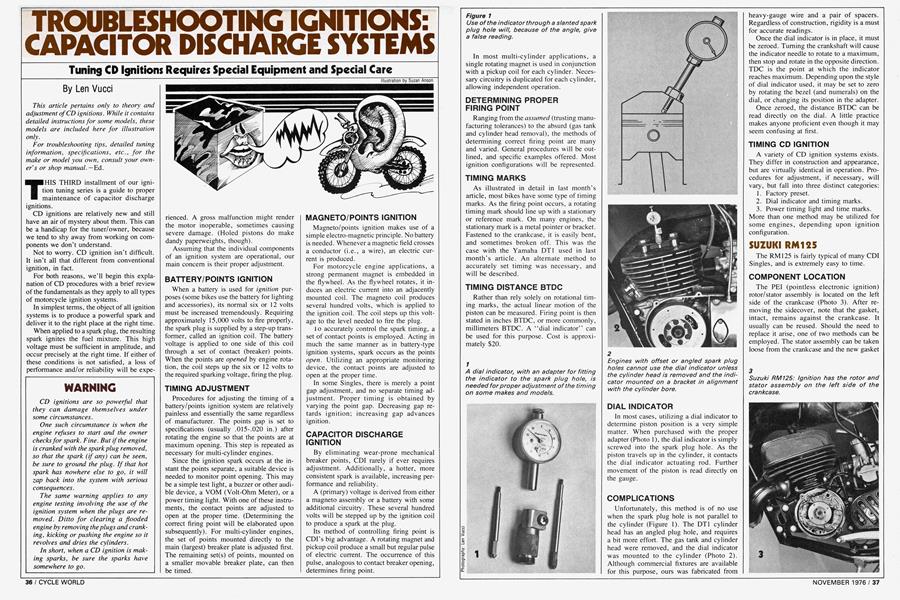
Figure 1
Use of the indicator through a slanted spark plug hole will, because of the angle, give a false reading.
In most multi-cylinder applications, a single rotating magnet is used in conjunction with a pickup coil for each cylinder. Necessary circuitry is duplicated for each cylinder, allowing independent operation.
DETERMINING PROPER FIRING POINT
Ranging from the assumed (trusting manufacturing tolerances) to the absurd (gas tank and cylinder head removal), the methods of determining correct firing point are many and varied. General procedures will be outlined, and specific examples offered. Most ignition configurations will be represented.
TIMING MARKS
As illustrated in detail in last month’s article, most bikes have some type of timing marks. As the firing point occurs, a rotating timing mark should line up with a stationary or reference mark. On many engines, the stationary mark is a metal pointer or bracket. Fastened to the crankcase, it is easily bent, and sometimes broken off. This was the case with the Yamaha DTI used in last month’s article. An alternate method to accurately set timing was necessary, and will be described.
TIMING DISTANCE BTDC
Rather than rely solely on rotational timing marks, the actual linear motion of the piston can be measured. Firing point is then stated in inches BTDC, or more commonly, millimeters BTDC. A “dial indicator’’ can be used for this purpose. Cost is approximately $20.
DIAL INDICATOR
In most cases, utilizing a dial indicator to determine piston position is a very simple matter. When purchased with the proper adapter (Photo l), the dial indicator is simply screwed into the spark plug hole. As the piston travels up in the cylinder, it contacts the dial indicator actuating rod. Further movement of the piston is read directly on the gauge.
COMPLICATIONS
Unfortunately, this method is of no use when the spark plug hole is not parallel to the cylinder (Figure 1). The DTI cylinder head has an angled plug hole, and requires a bit more effort. The gas tank and cylinder head were removed, and the dial indicator was mounted to the cylinder (Photo 2). Although commercial fixtures are available for this purpose, ours was fabricated from
heavy-gauge wire and a pair of spacers. Regardless of construction, rigidity is a must for accurate readings.
Once the dial indicator is in place, it must be zeroed. Turning the crankshaft will cause the indicator needle to rotate to a maximum, then stop and rotate in the opposite direction. TDC is the point at which the indicator reaches maximum. Depending upon the style of dial indicator used, it may be set to zero by rotating the bezel (and numerals) on the dial, or changing its position in the adapter.
Once zeroed, the distance BTDC can be read directly on the dial. A little practice makes anyone proficient even though it may seem confusing at first.
TIMING CD IGNITION
A variety of CD ignition systems exists. They differ in construction and appearance, but are virtually identical in operation. Procedures for adjustment, if necessary, will vary, but fall into three distinct categories:
1. Factory preset.
2. Dial indicator and timing marks.
3. Power timing light and time marks. More than one method may be utilized for some engines, depending upon ignition configuration.
SUZUKI RM125
The RM 125 is fairly typical of many CDI Singles, and is extremely easy to time.
COMPONENT LOCATION
The PEI (pointless electronic ignition) rotor/stator assembly is located on the left side of the crankcase (Photo 3). After removing the sidecover, note that the gasket, intact, remains against the crankcase. It usually can be reused. Should the need to replace it arise, one of two methods can be employed. The stator assembly can be taken loose from the crankcase and the new gasket slipped over it. The stator assembly can then be replaced. A more expedient way is to carefully slit the gasket across one of its screw holes so that it can be slipped over the lead wires. Gasket integrity can be retained by the use of a dab of sealant at the cut.
TIMING ADJUSTMENT
Timing on the RM 125 is preset at the factory, and should normally not need adjustment. If necessary, timing is adjusted by rotating the stator assembly. Loosen the two hold-down screws, then turn the base plate until the timing mark aligns with the top screw (Photo 4. Note that the screw itself has been removed for clarity). Tightening the hold-down screws completes this procedure.
CAN-AM 250 T'NT
The Can-Am is a single-cylinder bike that utilizes Bosch CDI components, but in a rather unusual configuration. The result is aesthetically pleasing as well as functionally convenient.
COMPONENT LOCATION
The CDI coils are mounted on the inside of the right crankcase cover. A plastic inspection plug, removable with a coin or screwdriver, provides visual access to the timing marks (Photo 5).
TIMING PROCEDURES
There is a reference mark on the crankcase cover itself, just inside and at the lower edge of the inspection hole (Photo 6). This should align with an adjacent mark on the stator assembly. Unless one wishes to verify the accuracy of these marks with a timing light or dial indicator, the inspection plug may now be replaced.
DIAL INDICATOR METHOD
Elevate the rear wheel and place the transmission in fifth gear. The engine can then be rotated in either direction by turning the rear wheel.
A dial indicator is inserted directly into the spark plug hole, then zeroed at TDC. Rotate the engine until the flywheel timing mark aligns with the reference mark (Photo 7). Timing should be 1.4mm BTDC.
ADJUSTING STATOR
Should retiming be necessary, the cover and attached stator assembly must be removed. Four Allen-head cap screws secure the cover to the crankcase. Lifting the cover away from the crankcase reveals the stator assembly and flywheel (Photo 8).
To change stator position, hence timing, loosen the two Allen-head retaining screws and rotate the stator to the desired position. Tighten the screws, replace the cover/stator assembly, and recheck. Repeat as necessary until proper timing is obtained. Replace the four Allen screws and inspection plug.
TIMING LIGHT METHOD
Hook up the power timing light and start the engine. Hold the revs to a steady 6000 rpm, and direct the light at the inspection hole. Flywheel and reference marks should be in alignment. Follow the procedures outlined above if a change is necessary. Be sure to recheck timing befbre final reassembly.
KAWASAKI KH400
Surprisingly, the KH400 Triple is nearly as easy to set up as a Single. It is equipped with a Kokusan CDI system, rather than the Mitsubishi system of the HI 500 and H2 750.
COMPONENT LOCATION
The CDI flywheel and coils are accessible by removing the left-side crankcase cover (Photo 9). There is little if any adjustment necessary, as timing should remain accurate unless physically disturbed.
TIMING MARKS
As on the Suzuki RM 125, timing marks on the stator assembly should align with a hold-down screw. Perhaps to discourage tampering, the three hold-down screws are partially covered by the flywheel. To change timing, one must first remove the flywheel with a puller. After loosening the hold-down screws, the stator assembly may be rotated to the desired position. If a dial indicator is utilized, the flywheel and reference mark should align at 2.6mm BTDC (Photo 10).
Unless the left side of the engine is damaged in a crash, this system should stay in time almost indefinitely.
KAWASAKI H2 750
Although the H2 entails a bit more work to set up, its components are easily accessible, and readily adjustable. Manufactured by Mitsubishi, the system’s performance meets the requirements of this truly awesome machine.
COMPONENT LOCATION
Remove the round cover on the left side of the crankcase to expose the rotor and three pickup coils (Photo 11). Clockwise, from the top, the coils are: center, right and left.
TIMING ADJUSTMENT
After removing spark plugs, rotate the engine so that the projection on the rotor is adjacent to the projection on any pickup coil. This gap should be .020-.031 in. (Photo 12). Adjust this coil if necessary, and repeat for the other two.
Utilizing a dial indicator in the left cylinder, position the piston at 3.13mm BTDC. The pointer on the stator assembly should be aligned with the “L” mark on the rotor (Photo 13). Turn the rotor so that the “S” mark aligns with the pointer (Photo 14). The trailing edge of the rotor projection should coincide with the left coil timing mark. Adjust the coil if necessary. This procedure is repeated for the right and center cylinders.
TIMING LIGHT CHECK
At this point, the ignition should be set up properly, but one may wish to ensure its accuracy with a power timing light. After replacing the spark plugs, connect the timing light to the left cylinder. With the engine running at a steady 4000 rpm, the “L” rotor mark should align with the stationary pointer (Photo 15). Repeat this operation for the center and right cylinders. So much for the H2 timing procedure.
CONCLUSION
This completes our discussion of ignition systems. Our intention was to remove the fear of tuning your own motorcycle. We realize that we did not cover every model, or even every brand. But we did expose you to all the various types of ignition: battery and coil, magneto and coil, and CDI. And we included examples of Singles and Multis in each section.
At this point you are on your own. All you need is a shop manual for your own bike, some tools that should not exceed the cost of a single dealer tune, and enough time to do the various steps carefully. If you recheck your work, you’ll be successful the first time out. And the first time is the worst. After that, your increased confidence and skill will make the job easy.
As we mentioned earlier, ignition is the major part of a tuneup, but not the only part. Carburetor adjustment is equally important. Same goes for setting the valves in fourstrokes. Then there is the chassis lube, brake adjustment and the like.
In time, we’ll cover all of these maintenance areas. In the near future look for an article on carburetor theory, adjustment, and rebuilding.