Forty Years of Development
FORTY YEARS OF DEVELOPMENT
GORDON H. JENNINGS
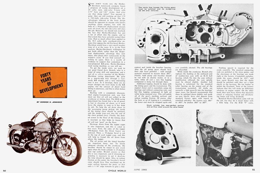
SOME FORTY YEARS AGO, the HarleyDavidson motorcycle company began a program of racing development on a 45 cubic inch, side-valve V-twin with 2.75" bore and 3.81" stroke. And what are they doing today? You guessed it, gang: they are still working on that 2.75 x 3.81-inch, side-valve V-twin. The disadvantages inherent in the basic design should be apparent to anyone who knows anything about engines, but with the help of a 50-percent displacement margin over all rivals, the old side-valve still does the job. However, we should not overlook the fact that Harley-Davidson has put a lot of effort into the engine, and to that extent they have certainly earned their wins. Had as much effort been applied to the 30.5 cubic inch, overhead-valve engines that oppose the old flat-head, HarleyDavidson would have a very much tougher time of it at the races. It is, in the final analysis, Harley-Davidson's willingness to put forth effort, rather than the 50-percent displacement advantage they now enjoy, that places their motorcycles in the winner's circle. If you find yourself unwilling to agree, there is a wealth of evidence to support that contention in a race-prepared KR-series Harley-Davidson road racing machine, as you will see.-
To get the inside story, we went to our good friend Jerry Branch, who is a tuner of some skill and reputation, and a sort of ex officio member of the HarleyDavidson racing department. He gave us a step-by-step tour through a raceready KR engine, and a very interesting tour it was. As it develops, there are no major changes one must make in the KR engine; but the amount of detail hand fitting is enormous, and that is what makes them go.
Starting with a completely disassembled engine/transmission unit, you first must see that oil will not collect in the crankcase or timing chest. The H-D racing department has found that a lot of power is lost in churning oil about, so it must leave the engine as soon as it has done its job. To help the oil drain down to the scavenging pump pickup, the inside of the timing chest should be polished, and the sludge trap cast into the end of the chest ground away. Finally, the domed screen in the floor of the timing chest is inverted, so that helps to insure that oil will not "pool" on the floor.
Drainage down from the tappet cages is also important, and this is aided in two ways. First, the sides of the tappet (90-degrees from the thrust faces) are relieved. Then, a 35-degree bevel is cut in the top of each tappet cage, and this will help to funnel the oil down from above the tappet.
The oil pump and the timed breather are important items, too. To insure adequate clearing of the crankcase, the breather should be timed to just crack open when the front cylinder is 25-degrees past top center. Branch assures us that this is very important, and if shimming or grinding is necessary to get it dead-on, the time should be spent. Also, to reduce friction at this point, the breather's barrel rotor should have flats machined on its outer surface between the ports, so that only a 1/16" edge remains to give a linecontact seal inside the breather housing. Also the oil pump gears should have their side faces polished — with enough material removed to narrow them .001". Finally, both pump and breather should be run with an electric motor, or in a lathe, while oil and a very fine lapping compound is being fed through them.
Additional lapping should be done with the timing gears and the transmission. The engine's lower end is assembled, using old bearings and without connecting rods, and fed fine lapping compound in light oil while being motored over. This will polish all of the gear's meshing surfaces and reduce running friction. Of course, after the hour or so of lapping-in is completed, the lower end must be stripped again and
very carefully cleaned. The old bearings are discarded.
While inside the crankcase. Branch also replaces the bushing at the outboard end of number-two cam with an R-10 ball bearing, which fits into the case without modification although the cam spindle must be altered slightly. Another ball bearing is substituted for the standard roller bearing on the output end of the transmission mainshaft. All shafts are normally a light press-fit into the bearings' inner races, but Branch recommends that these be polished down slightly and made an easy slip-fit. Jerry also departs from standard factory specs with regard to camshaft end-play: the factory says .001" to .005"; he prefers .005" to .007".
Nothing special is required for the crank assembly. The standard connecting rods are polished at the stress points, and the clearances at the bearings are made right at the factory. Crankshaft end-play, inside the cases, should be .022", and here again Branch says that the shafts should be polished until they are a light slip-fit in the bearings. Do not bother to polish the flywheels. Tests at the factory indicate that this will make no difference whatever in engine output. On the otherhand, their tests have shown that measures aimed at reducing friction and oil-churning losses will bring dividends.
Standard Harley-Davidson cams will do the job, but they do it much better with a little help. Use the H-D "F" cams. which have the following timing: Intake opens 66-degrees BTC, closes 66degrees ABC. Exhaust opens 56-degrees BBC, closes 42-degrees ATC.
In some engines, the cams will give this timing without any fiddling, but in most cases some adjusting will be required. The problem is not so much in the cams (which are indexed fairly accurately to their gears), but in the cambearing bores in the crankcase, which are usually not on precisely the correct centers. When they are off, the cams' gearmesh is also off, and the added gear lash will move the timing somewhat. This can be corrected by juggling tappet clearances, in which case you should try to get the correct overlap, rather than the valveopening points. In short, time for the 66-degree BTC opening of the intake, and 42-degree ATC closing of the exhaust.
Obviously, juggling tappet clearances is something short of the optimum method and the really correct method of setting the timing is to cut the cams from their gears and weld them back — positioned so that the timing is correct. This is admittedly, a difficult job. You must grind through the hard-case between the cam and the gear, and then cut the cam free on a lathe. Because the original part is a press-fit on the cam spindle, you can press the two pieces on a new spindle (use an old one for this cutting operation), assemble them in the engine, bump them around until the timing is perfect, and then remove and arc-weld in position. Extreme care must be exercised in the welding starting behind the cam lobe, and working very fast to avoid heating the cam so much that the hardness is lost.
While working on the valve gear, you can lighten the follower assembly by grinding the adjuster screw hex-head and the lock-nut to a smaller size. Branch also cuts the follower's roller-width by twothirds, taking a third from each side.
While it has long been accepted that a "tuliped" valve was the thing to have — on the assumption that the large radius where the stem joins the head gave a streamlined flow - Harley-Davidson's development engineers have discovered the opposite to be true. A very flat valve head is what they like, with just enough radius at the base of the stem to keep the valve head from breaking off. Such a valve is lighter and their tests show a clear superiority in air-flow capacity.
The stock valves should be used, but here, too, handwork will pay in horsepower. The valves should seat right out at the very edge of the valve-head, and the seating line should be just 1/16" in width. After the seating line is established, the back of the valve head should be trimmed, starting at the stem radius and working outward. Then, after this thinning operation, the valve should be polished to remove all tool marks.
The corresponding narrowing of the valve seat is done with a 45-degree stone, and after this relief is cut, it is advisable to blend the cut into the rest of the port. The valve seats themselves are cut at 30degrees, which is an archaic practice — but then we are dealing with an archaic engine. You will find that the ports are quite good, and apart from a bit of fine polishing, if you are feeling particularly ambitious, need no attention. Do not work at them with a grinder, as their shape is critical, and it is correct as delivered from the factory. Especially, avoid the temptation to trim the valve guides, as this will shorten the guides too much and allow the valve heads to rock on their seats.
Use the factory valve rotators, as this will prolong seating life and keep the engine healthy through a long race. Also, stick with the factory KR racing valve springs. Spring packing should give 1 3/16", measured between upper and lower collars, on both intake and exhaust valves. The intake lifts slightly more than the exhaust, and one might think the packing should be different, but the intake valve is also slightly heavier and that little bit of extra tension at full lift helps.
Having its valves in a pocket beside the cylinder bore, rather than above it, the KR engine is afflicted with a real breathing problem, and you must give close attention to this part of the job at hand. The latest cylinders have "reliefs" but between the valve heads and the bore, and apart from a bit of polishing and removing of sharp edges, they should be left alone. A tremendous amount of experimental work has gone into the shaping of these flow channels, and it is unlikely in the extreme that you will improve the flow by re-shaping. However, it is necessary to make a paper pattern of the relieved area, which is used to scribe a matching area on the underside of the cylinder head. The pocketed area above the valves is then trimmed to match. Use the late-type #7 cylinder head, as it works better with the late cylinder.
When installing the heads, there are several clearances around the valves that one must watch. First, on the late-type heads, the pocket behind the valve heads (away from the bore) is slightly cupped. This directs gas-flow around and over the top of the valve; in effect, bringing into use all of the valve circumference. And, because a substantial part of the gasflow is over the top of each valve, clearance between the valve head and the top of the combustion chamber is critical. With the intake valve in full-open position, there should be .090" between valve head and combustion chamber; for the exhaust valve, the figure is .040". If there is too little clearance, re-seat the valve to sink it the required difference; too much clearance means machining the face of the head to bring the top of the combustion chamber down - which will ultimately require that you also re-machine the combustion "squish" area. Incidentally, that pocket behind the valve heads must be 1/16" in depth for the intake valve; 1/32" at the exhaust.
All of this work must be done in conjunction with the installation of the pistons — which is not just a simple matter of dropping them into the bores.. Jerry Branch likes Harley-Davidson's standard K or KH pistons, as they are lighter than the racing pistons and can be fitted a bit tighter (.007"). This minimizes piston rocking, and that helps ring-sealing considerably. For those who think that a racing engine should have some sort of special racing pistons, Branch points out, with a lot of logic, that the KR engine will not breathe properly if the combustion chamber is squeezed down, and that with the resulting 6.13:1 compression ratio, very little heat is being put into the pistons. They have an easy life, and there is no need for anything exotic.
When installing the pistons, the cylinders must be shortened (by machining material from the base) so that at top center, they pop-up 3/16" above the bore. Standard is 1/8", but with more pop-up you get a wider channel between the valves and the cylinder itself. In conjunction with this change in pop-up, you must machine away about .050" in the combustion chamber above the piston. Take enough material to give .035" clearance between the piston crown at top center and the combustion chamber. This figure should be obtained by machining to a depth of .222" from the cylinder head face.
To compliment the change from .125" piston pop-up, to .187", the piston itself must be modified. Start by scribing a line across the middle of the piston crown, from front to back. Then, measure in 5/16" from the edge of the piston crown next to the valves and scribe again. Finally make a smooth arc around from front to rear on the piston crown, starting at the forward edge, swinging in to 5/16" next to the valves, and back to the edge again at the rear of the piston. After this is done, make a matching arc 3/16" deep on the side of the piston and file away the metal between the arcs to form a bevel. This bevel must be exactly to the specified pattern, for it affects both breathing and squish. Less bevel will cause a power drop; more will actually cause an overheating condition at the piston and cylinder head. This was discovered on instrumented engines, using thermo-couples and a dynamometer, at the factory.
We might mention that the standard heads have the edge of the squish-area angled rather sharply across the cylinder, relative to the fore/aft plant of the engine. Heads with this edge set almost parallel (in the plane just mentioned) will give slightly more power, but the angle becomes critical to 2-degrees when this is done, and the heads must be tailored to the particular cylinder on which they are used. For that reason, the angled-edge squish area is used, as it is tolerant of fairly wide variations in area and angle. Standard heads have a sort of "deck" near the tips of the cooling fins to stop these from ringing when the engine is running, but Branch cuts this away and drills the fins themselves full of holes to save weight. He also cuts a slot in the fins at each side of the exhaust port to block heat flow away from the port area, and removes as much metal as possible from the exhaust port stub to prevent heat flow from the port back to the cylinder.
The KR's intake manifold is a short, stubby "Y", and while it is given a good internal polishing at the factory the arms of the Y angle out to the ports rather sharply. You can correct this by brazing-on material at the sides of the manifold, and then grinding out the interior to give a less abrupt change in flow.
The latest KR carburetor requires little modification apart from thinning the butterfly. You should use two main-jets: one being a fixed jet, with a .052" orifice; the other the normal adjustable high-speed jet. Feeding fuel into the emulsion chamber from two sources helps the atomization process. Also, add an extension on the float chamber. Weld on a 2" piece of 3/4" aluminum tubing to give an increase in volume. This will help in holding the float level during hard acceleration and thus prevent mixture leaning-out. Earlier carburetors may be brought up to latest form following instructions available from Harley-Davidson's racing department.
Between the carburetor and manifold, add spacers and gaskets to give an extra 7/8" of length. The best method is to make this of some hard fiber material, but Branch gets the same results with an aluminum spacer and thick teflon gaskets. Apart from the length, which seems to "tune" the intake system to the cams being used, the object of the spacer is to block heat flow to the carburetor.
There is also an increase in power to be had by building an air-flow bell at the point where the carburetor joins with the air-cleaner. Branch does this by adding an aluminum ring, which has a 3/8" radius machined in its bore. He says it gives a noticeable boost in power all through the range. It is worth mentioning that other carburetors have been tried, by the factory, but that the 1 5/16"-bore, L and L carburetor now being used gives the best overall results. Boring to 1 3/8" gives an increase in peak power, but is not worth the drop in power through most of the range. Actually, the standard carburetor has only two disadvantages: first, it looks borrowed from a farm tractor; second, the butterfly pivots on a vertical shaft, and thus tends to give a bias to mixture flow when running on part throttle. Neither of these seriously affects its performance on a racing engine.
The standard magneto is sufficient to the task, but virtually all have one defect: the breaker-cam lobes ahe not perfectly indexed. To check and/or correct this, install the magneto and, after removing all leads from the points, time the pointbreak to 36-degrees before top center on the front cylinder. Use a 6-volt battery and a small light-bulb to tell you when the points are closed. Then crank the engine over until the light shows that the points are breaking for the rear cylinder and check to see where the magneto fires, relative to crank position. If it is not at 36-degrees BTC, polish away the breaker cam with a small, fine stone until it does fire at the proper time. The point gap should be set at .012".
Do not use premium-grade gasoline in the KR engine. With the very low compression ratio, it likes regular-grade fuel much better. Castor oil, in 45-weight, is a good lubricant, Branch says, and has the advantage of not coloring the plugs to give a false mixture reading. Branch also tells us that a properly set-up KR will eat oil at the phenomenal rate of almost a gallon per 100 miles. To get maximum power, everything is set to rather loose clearances, and oil is pumped through at a ferocious rate to carry heat away from the bearings, and that accounts for the high oil consumption.
The engine should be stripped and inspected after each race, just to make certain that everything is in good order. One thing you should remember is that piston crowns, combustion chambers and exhaust ports should not be polished. A light layer of carbon will prevent heat from sinking into the metal. You can remove large flakes of carbon, but leave the rest. If this is removed, there will be a power drop until the carbon layer has re-formed. This may not sound right to a lot of people, but it is a fact confirmed by testing at the factory.
An average KR engine will develop 48 bhp, right out of the crate, and that is not bad. However, this climbs to 52.5 bhp after the full treatment, as we have described here. The treatment must include a light rebore after the initial running period, as the cylinders will settle slightly and need the rebore to eliminate distortion.
It may occur to you that all of the work we have described is "only" worth 4.5 bhp. It should not be necessary to point out that this can, and often does, make the difference between winning and finishing back about 10th. Perhaps the most •significant fact in all this is that all of the work does yield an increase of 4.5 bhp. This tells us that the factory really has brought the engine to a high level of development, and it is a matter of record that those who attempt to second-guess the factory on many points lose power, not gain it. It is also significant that Harley-Davidson has brought the basically 40-year-old KR along so far. It pushes out over 1 horsepower per cubic inch in "stock" form, and does this in the face of overwhelming handicaps in breathing (due to the side-valve layout) and piston speed (due to the 3.81" stroke.) These engines pull strongly to 7000 rpm, which has staggering implications in terms of volumetric efficiency with a fundamentally inferior valve layout, and they are reliable in the face of 4500 feet per minute piston speeds. Given an engine with fewer built-in disadvantages, this much development effort at Harley-Davidson could give them a 30.5 cubic-inch engine that would offer an even greater edge in HarleyDavidson horsepower than the one now provided by the irksome 50-percent displacement advantage. •