Bright Headlights For Your Bike
BRIGHT HEADLIGHTS FOR YOUR BIKE
Part 2: A Fix for Every Road Machine
Len Vucci
With few exceptions, the evolution of the modern motorcycle has not included the adaptation of a better headlight system. The standard sealed beams with which most road bikes are equipped are behind the times, and only adequate, at best. A substantial improvement in night vision and safety can be had by installing a superior quartz-halogen lamp.
As you may know, the QH headlight system is better in a multitude of respects. By using quartz glass instead of the garden variety silica stuff, higher filament temperature and thus brightness, is possible.
Additionally, a typical QH reflector gives a beam pattern which provides better driver vision, while reducing the amount of glare for oncoming motorists. In every respect, the quartz-halogen unit overshadows a sealed-beam headlight.
Why don’t more bikes come equipped with QH lights? Cost is one factor. The sealed-beam can be produced at a very low price, and can be bought retail for as low as two bucks. The current retail price of a QH bulb and reflector assembly might run as high as $25 with spare bulbs going for about $10. Motorcycle manufacturers, in an attempt to keep costs to a minimum, equip only a few' of their most expensive offerings with the more costly units.
If you wish to improve upon your present lights, the conversion to quartz is THE way. Vehicle codes for your state should be consulted to determine the legality of such a swap.
CONVERSION METHOD, 12-VOLT SYSTEMS
The switch to QH lights will entail different levels of skill and finances, depending upon what type of electrical system is on your bike.
If the stock headlight is a 12-volt unit, be it of the sealed-beam or separate-bulb variety, odds are the swap w ill be easy. The typical rating for an OEM lamp is 50 watts, with several units dipping down into the 40-45 watt range. The headlight reflector will have a diameter of either 53A or 7 in.
A quartz unit of the proper diameter can be installed in exactly the same way as an OEM replacement. The QH bulb, which is rated at 55/60 w'atts (lo-/hi-beam). draws little more current than did the stocker, so the existing lighting system should have no trouble providing the extra juice. (The author’s elderly Triumph, which came stock with low-power lighting, now throws a strong QH beam, and the battery lives on.) Nothing could be simpler.
If your bike has a 6-volt lighting system, the conversion to quartz will more than likely require some extra work, and a few more dollars.
CONVERSION METHOD, 6-VOLT SYSTEMS
Most contemporary 6-volt lighting systems utilize a headlamp rated at 30 or 35 watts. The magneto’s lighting coils are designed for this load, and will supply between 6 and 7 volts under normal operating conditions.
The logical QH update would seem to be to procure a 6-volt quartz headlamp, and substitute it for the original. Trouble is, this will work only for a few bikes.
If the headlight can be turned on when the engine is not running, the battery is the source of power, and the engine’s magneto is used to keep the battery fully charged. (The Kawasaki KL250 has such a system.) A 6-volt QH lamp may be substituted for the stocker only in this case. There is one drawback. The additional load imposed by the heavier bulb can cause a depletion in the battery’s charge if it is constantly turned on. If a substantial portion of your riding is done with the lights on, you may have to keep the battery on a trickle charger between rides to maintain an adequate voltage level.
If your engine must be running in order to operate the headlight, a different type of conversion becomes necessary. The battery does not power the headlight in such systems; instead, it is used for all other electrical components. The magneto serves two separate functions: It powers the headlight and charges the battery. Since the battery is not a reserve source of power for the headlight, a simple swap is not possible, as the magneto alone cannot provide enough oomph for the more demanding quartz unit.
For example, a stock Yamaha XT500 will provide nearly 7 volts to the stock headlight under normal operating conditions. When a 6-volt, 55-watt QH headlight was installed, the maximum voltage dropped to less than 5 volts. This may not seem like a big drop at first, but in terms of power, which varies as the square of the voltage, that’s a 50-percent loss. In terms of cost vs benefit, it’s a total loss.
We’re back to Square One. How does one boost the light output of a 6-volt system? Simple, almost. We can use the same principles we applied in the off-road lighting hop-up we did in our May, 1978 issue, with several additions to adapt the conversion to road bikes.
In essence, the solution involves sub stituting a 12-volt QH bulb for the original 6-volt unit. No need to get into a lengthy tech discussion about why it works, suffice it to say it does. In fact, the stock 6-volt lighting coil, in many cases, will supply more than 55 watts to the 12-volt QH bulb, and must be regulated to prevent bulb burnouts. Once the 12-volt QH bulb is installed, the headlight circuit is converted to 12-volt operation.
This leaves us with a different problem. because the rest of the bike's electrical components are still 6-volt items. There are two ways by which the system may be made compatible. All the components can be swapped for 12-volt items. These in clude taillights, turn signal lights, instru ment lights and battery. What you have, in effect, is the same basic electrical system as stock, but it now is a 12-volt operation.
The alternate method, which we'll illus trate using a Yamaha XT500. is far more simple. First, the headlight circuit is con verted to 12-volt operation, and a voltage regulator is used to prevent bulb burnouts. A heavy-duty resistor is then used to drop the headlight's 12 volts down to 6, provid ing a source to keep the battery charged. and operate the turn signals, tailand brakelights, et al.
This all may seem a bit unclear at first, but as we progress through the conversion a step at a time it will make much more sense.
NECESSARY EQUIPMENT
For conversions other than the straight sealed beam/QH swap, you'll need basic hand tools, and several electrical tools. An AC voltmeter is required, as is a soldering iron or gun. Resin-core (not acid-core) solder, some heat-shrink tubing and a few assorted odds and ends complete the list. The exact items will be determined by nature of your particular conversion, and will be evident as we progress. If your conversion requires a magneto modifica tion, we'll be referring you to our May, 1978 issue for explicit instructions. And a copy of the bike's owner's or workshop manual will most likely be necessary.
PROCEDURAL BACKGROUND
Those of you whose bikes require only that the headlight be swapped should al ready be finished. The rest of you should begin by removing the stock headlight from its shell, and the side covers and seat, if necessary, to gain access to the wiring. Now the fun begins.
Armed with a copy of your owner’s or shop manual, you must first determine the type of lighting circuit the bike has. You may need some help deciphering the wiring diagram if it is small and crowded, and a peek at the actual lighting coils and wiring can help make things more clear. There will be several coils in the magneto, so use the manual to determine which is for lights, which is for ignition, and the colors of the wires leading to each.
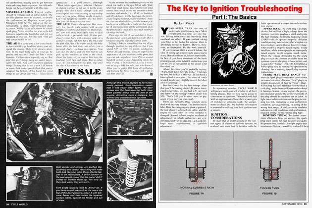
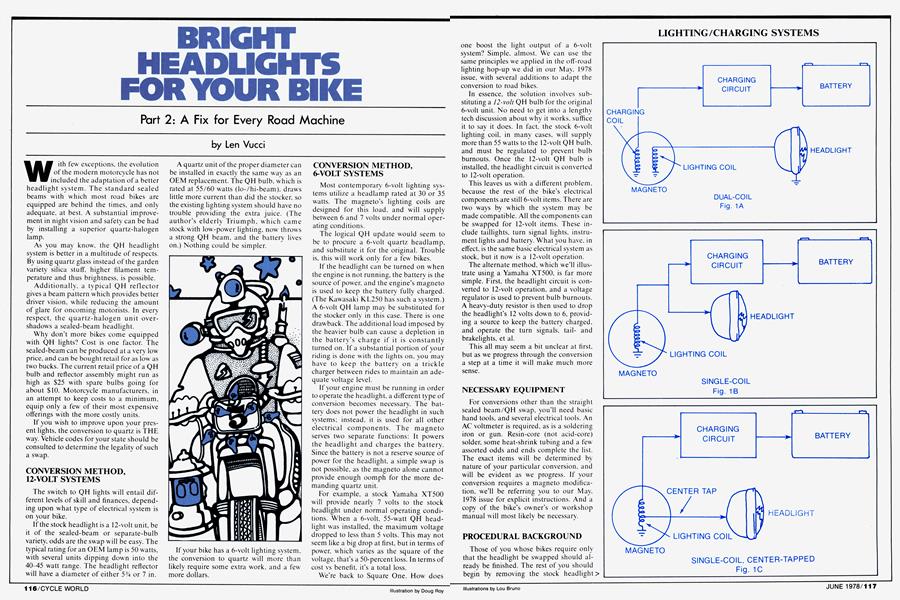
The electrical configuration of the coils on your bike should resemble one of those shown in Fig. 1. Some bikes, such as Honda XLs, early Suzuki TS models and late Yamaha DTs, use one coil for running the headlight and another for charging the battery (which powers the lights and horn). This circuit, shown in Fig. 1A, is easy to modify. Since the headlight operation is independent of the charging system, the lights can be boosted while the charging circuit is left stock.
In the single-coil system, represented by Fig. IB, both headlight and charging systems are operated from the same source. (Early Yamaha DTs, for example, use this type of circuitry.) Since these two functions share a common circuit, modification of one part of the circuit will have an effect on the other. Thus, a headlight mod will also require a change in the charging circuit.
Finally, we have the single-coil centertapped circuit, shown in Fig. 1C. One coil produces current for headlight and charging, but each is tapped off at a different point on the coil. Although the coil has two separate outputs, the headlight and charging systems are interdependent. As with the non-center-tapped coil, a modification of the headlight circuit must be accompanied by a modification of the charging circuit.
To illustrate the modification of a single-
coil system, we’ll be using a Yamaha XT500. The XT, which has a 6-volt system fairly typical of dual-purpose street-legal bikes, can be ridden at speeds which all too soon exceed the performance capabilities of the stock 35-watt headlight. It is equipped with the full complement of street lights and gear, including horn and battery, and poses most of the problems which must be overcome for a conversion of this type.
(Note: To make the conversion of the Yamaha XT500 sanitary and easy, and to simplify the procedure for the non-XT owners, we’ll keep the main text as general as possible. Specific conversion details for the XT will be given at the end of the general text, in the section entitled YAMAHA XT500 CONVERSION.)
BASIC TEST SETUP
Remove the stock headlight, if you’ve not already done so, and install a 12-volt unit. Although a QH unit will be used, it’s a good idea to spend an extra two bucks for a sealed beam. Use the SB for setting the system up; if you should make an error and blow a bulb, you’re only $2 behind, not $10.
An AC voltmeter must now be connected into the headlight circuit, so voltage to the new bulb can be monitored (Fig. 2). The voltmeter should be set on a scale which will give an accurate reading for 1015 volts. For most meters, this will be the 20-, 25-, or 50-volt scale.
HEADLIGHT ISOLATION
Before making any voltage checks, we must first ensure that the charging system will not interfere with the headlight operation. If your bike has a dual-coil system, you need not worry, as they are independent. If the bike has a single-coil system, the charging circuit must be temporarily disconnected. For the Yamaha XT, this was
accomplished by unplugging one of the two wires leading to the rectifier, located beneath the left side cover. In addition, the 6-volt regulator had to be removed from the lighting circuit. Its original purpose was to limit the headlight voltage to about 7 volts, but would defeat the 12-volt conversion if left intact.
For single-coil systems other than the XT, the points at which you disconnect the charging circuit will vary; just make sure the headlight circuit is intact, but that all else, including stock regulator, if present, is disconnected.
HEADLIGHT VOLTAGE TEST
Start the engine, but do not rev it above a fast idle. With the headlight on high beam, slowly bring the rpm up, while watching the reading on the voltmeter. Most likely, the voltage will increase quite rapidly, and approach 14-15 volts well before the engine’s maximum rpm is reached. Do not rev the engine higher or you’ll burn out the headlight.
You should have observed one of three conditions:
(A) The voltage reached 14-15 volts before maximum engine rpm, but would have risen higher with an increase in rpm.
(B) The voltage was substantially less than 13 volts, even at maximum engine rpm.
(C) The voltage reached 13-14 volts at maximum rpm but went no higher.
The next course of action will vary, depending upon which voltage reading you observed. If condition C was the case, you should proceed to the section entitled CHARGING CIRCUIT HOOKUP, unless your bike has a dual-coil system. If it does, change the high-beam indicator lamp to a 12-volt unit. Your conversion is now complete. continued on page 122
continued from page 118
If conditions A or B were observed, there are still modifications to the lighting circuit which must be performed.
CONDITION A: EXCESS VOLTAGE
When a 12-volt bulb is installed, most 6volt lighting circuits will produce an excess amount of power, and must be regulated to eliminate bulb blowing. Such was the case for the Yamaha XT500, whose stock lighting system would produce well over 16 volts under these conditions. A regulator had to be installed to limit voltage to a safe level.
Regulators can be obtained from most of the Japanese bike manufacturers; we’ve had excellent results using an Americanmade unit from Henter Engineering in Florida. (A list of distributors for the Henter regulator can be found in the Off-Road Lighting article in our May, 1978 issue.)
The regulator must be wired in parallel with the headlight, as shown in Fig. 3. The manufacturer’s instructions should be followed to ensure adequate electrical conduction and heat dissipation.
Once the regulator is properly wired, the owners of Condition A bikes should proceed to the section entitled CHARGING CIRCUIT HOOKUP.
CONDITION B: INSUFFICIENT VOLTAGE
If the reading you obtained from the headlight voltage test was insufficient, the magneto lighting coil must be modified. The procedure for boosting the output of the lighting coil is relatively simple. As is the case for other simple operations, however, the explanation for this mod is quite lengthy. Since we outlined in detail the necessary info in our May, 1978 issue, it’s best we refer you there, instead of duplicating the method here. The section called FIX #3 is the appropriate starting point.
Once the lighting coil has been modified to produce the correct 13-14 volts, you should install a 12-volt high-beam indicator lamp, then proceed to the next section.
CHARGING CIRCUIT HOOKUP
At this point, you should have a bike with a lighting coil providing 13-14 volts to the headlight, but with no connection to the charging circuit. And there is now a voltage mismatch between the 12-volt headlight and the 6-volt charging system.
If you were to connect the two directly, you’d have, essentially, an electrical system much the same as stock—except the headlight would glow only dimly. The 6-volt charging system would load down the headlight circuit, preventing the voltage from rising past 7 or 8 volts (Fig. 4A).
The solution is simple. We insert a voltage dropping resistor between the two circuits to allow the voltage differential to occur. The headlight then gets its full voltage, while the charging system, which requires less, receives less (Fig. 4B). This is
VOLTAGE DROPPING RESISTOR ASSEMBLY
an oversimplification, but the fact is, it works.
The value of the resistor you’ll need might vary slightly, so you might have to experiment a bit to arrive at the proper rating. For starters, pick up a 4-ohm, 10watt wire-wound resistor from your local electronics supply store. It may be available in several configurations, so pick the one which looks easiest to mount. We’ve found the tubular, hollow types to be appropriate, as they are mounted using a long bolt through the center. Cost will be between 50C and a $1, so don't be too concerned about bargain hunting. If you have a friend with a Honda XL, talk him into converting to QH—the 3.6 ohm lowbeam ballast resistor in his headlight shell is ideal, (With his dual-coil system, he won’t need it anymore.)
For a non-center-tapped lighting coil, one end of the dropping resistor is connected to end of the coil where the headlight circuit connects (Fig. 4B).
For a center-tapped coil, the end of the dropping resistor connects to the free end (not the center tap) of the coil (Fig. 4C).
The remaining end of the resistor connects to the charging circuit.
If the original lighting circuit was equipped with a 6-volt regulator, you can use it on the modified system. But instead of connecting it to the headlight, connect it to the charging circuit side of the dropping resistor. The regulator will then serve to prevent the battery from being overcharged.
ADDITIONAL MODIFICATIONS
The conversion is complete at this point, but you may wish to make several additional modifications to tailor the system to your bike.
When the Yamaha XT500 wras converted. we found that turn signal operation was improved by swapping the stock capacitive flasher for a 12-volt automotive unit. The bi-metallic flasher, besides being more consistent in operation, also causes the turn signals to draw less power, easing the burden of the charging system and battery.
If you do a lot of riding with the headlight on. you may find the battery to be slightly under charged, especially if your stop-and-go riding is mostly stop. Change the dropping resistor to a 3-ohm unit to raise the charge level. Lowering the resistance (numerically) of the dropping resistor increases charge rate, but may slightly decrease headlight brightness. One value between 2.5 and 5 ohms will be optimum.
This concludes the general portion of the text. We will now apply the procedures to the XT500.
YAMAHA XT500 CONVERSION
Although the procedures outlined above will be applied to the XT conversion, they will differ slightly in sequence. This is to allow us to utilize the wiring connectors which would otherwise have been discarded, and thus save a bit of gofering and change.
Remove the stock headlight from its shell, and replace it with a quartz-halogen unit. The headlight wiring is identical, so this is, literally, a bolt-on.
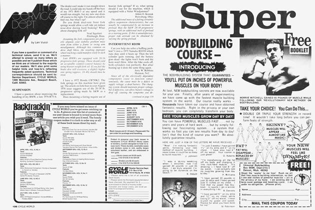
Remove the left side cover, and yank the stock flasher unit after disconnecting its three wires (Photo 2).
Cut the two brown flasher leads, leaving at least 34 in. on each connector (Photo 3). Retain the connector ends (male and female) you’ve just cut—you’ll need them shortly.
Install a female spade connector on each of the bike’s flasher wires, and plug in
a 12-volt auto flasher (Photo 4). Wrap a couple of layers of duct tape around the flasher unit, then place it in the stock rubber mount.
Slide a piece of shrink tubing over the lead of the voltage regulator, then solder the male connector (cut from the flasher wires) onto it. After shrinking the insulating tubing, it should appear as in Photo 5.
continued on page 142
continued from page 123
Cut two pieces of # 14 or # 16 wire, one 6and the other 7-in. long. Solder these wires onto the dropping resistor, then insulate the connections with shrink tubing to strengthen the joints.
Slide a female spade connector over both the long wire on the dropping resistor and the female flasher connector (Photo 5). Solder or crimp the connection securely. Fasten a male spade connector on the remaining wire of the dropping resistor.
Drop a 3-in. machine screw through the center of the dropping resistor, and fasten it with a washer and nut, and a dab of Loctite (Fig. 5). Tighten the nut snugly, but don’t overdo it—if you end up with a handful of porcelain chips it’s too tight.
Just to the front of the XT500’s battery is a rubber fuse box holder, with a hole in which a spare fuse is normally carried. Slip a washer over the end of the resistor screw, and slip the screw into the hole in the rubber fuse box mount. Put another washer on the bottom, followed by a nut and some Loctite, and draw the assembly > up snug (Photo 6). Route the two resistor wires inside the frame tube, where they’ll be connected later.
The final mechanical step is mounting the regulator. As shown in Photo 7, we
mounted it on the frame gusset just below the battery. We drilled and tapped two holes for # 10 hex screws, which worked quite well. An alternative would be to use nuts instead of tapping the gusset. For either method, remove all burrs and rough edges from the drilling, and sand the paint off where the regulator mounts. Put a light coat of grease on the frame, then mount the regulator. The grease will prevent rust and improve heat exchange between the regulator and the gusset. The wiring should now be connected to complete the conversion.
Locate the XT’s rectifier—it is about 3 in. below the flasher mount, nearly hidden from view, and has red and white leads attached. Pull the red lead's spade connector off the rectifier. Plug the female spade connector from the dropping resistor onto the male connector of the red lead. The remaining lead on the dropping resistor plugs into the terminal of the rectifier formerly occupied by the red lead.
Next to the rectifier is a metallic can from which a yellow/white wire stems. Unplug this wire from its female connector, then plug it into the female connector you wired on the dropping resistor lead.
Finally, plug the male connector from the new regulator into the female connector on the yellow/white wire.
If you’ve wired the circuits correctly, there will be no loose ends, and the conversion will look like a factory installation. What’s more, it’ll work like one too.
If you ever decide to sell the bike, but wish to retain the QH light and 12-volt regulator, restoration to the original 6-volt system is easy. Unplug and remove the headlight, voltage regulator, and dropping resistor. Reinstall the stock headlight, then reconnect the stock wires as they were originally. The system is now7 6-volt operational, the only difference from stock is the auto flasher unit, which works better anyway. É3