The Dynamometer
The Dynamometer
A Basic Look At A Useful Tool, Not Just For Measuring Horsepower, But For Creative Engineering.
JODY NICHOLAS
THE DYNAMOMETER, or "dyno," a modern device used for power measurement,derives from an idea far from new. As long ago as 1790, a device invented by de Prony was available for determining torque at a given rotational speed by braking.
Even today, all mechanical dynamometers are based on this simple principle. The dyno changes rotating torque to stationary torque, which can be measured.
Torque, in this ensc, means something which produces or tends to produce rotation or torsion and whose effectiveness is measured by the product of the force and the perpendicular distance from the line oj action of the force to t/ie axis of rotation.
A DEFINITION
Torque, simply stated, is the quant i ty of work an engine can perform, and horsepower is the measure of work performed over a given period of time. This period of time is expressed in revolutions per minute of the engine's era n k shaft.
the relationship between rpm, torque and horsepower can casily be studied with the aid ofa dynamometer. C arburetion adjustment, ignition ad vance, various fuels and exhaust systems can be analyzed with great accuracy, and development work can be per formed without leaving the worLshop.
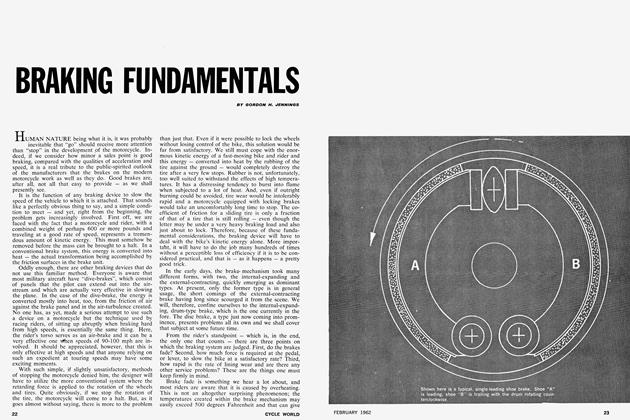
Several types of dynamometers are in use today, the most common of which are 1) the water brake. 2) the hydraulic brake. 3) the disc brake, and 4) the eddy-current brake. in each of these examples, a different medium is used to provide the braking force that drives the scale, or measuring device, which gives a readout of the test engine's torque.
In the water and hydraulic brakes, a fluid circulates through a pump-like apparatus, and the disc brake unit oper ates almost exactly like the disc brake on an automobile or motorcycle. But perhaps the most sophisticated and ac curate is the eddy-current dynamom eter. It offers the advantage of very precise power measurement of a wide variety of input sources (e.g.. piston engines, electric motors, steam engines, etc.), which may have differing rotat ion al speed or torciue characteristics.
THE SCHENCK DYNO
One of the best examples of the eddy-current dynamorneter is the Schenck, manufactured in Germany.
A serrated rotor is incorporated in a casting cradled in the trunnibn support bearings. The housing also contains the exciter winding and the heat ex changers. which are water cooled. A direct (DC) current flowing in the ex citer winding produces a magnetic field. This field is static in the teeth of the rotor poles and thus rotates with the rotor.
An equal and opposite magnetic field is introduced in the heat exchanger walls which face the rotor. This field is a pulsating one corresponding to the fre quency of the passing rotor teeth.
The changing field produces eddy currents in the heat exchanger walls which oppose the exciter field, thus causing a braking action on the rotor. The resultant energy in the forni of heat is simultaneously removed by the heat exchanger.
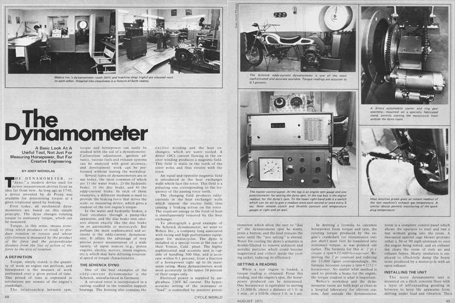
To photograph a good example of the Schenck dynamometer, we went to Webco Inc., a company long associated with racing and high performance equip ment for motorcycles. The dyno is installed in a special room at the rear of their Venice, Calif. plant. The highly sophisticated and accurate unit is cap able of handling 300 bhp, and is accu rate within 0.1 percent, from a fraction of a horsepower right up to its maxi mum rating. Many dynamometers work most accurately in the upper 50 percent of their ranges only.
Electrical power is supplied by single-phase 220V AC current. The hyperaccurdte setting of the resistance or "load" is controlled by sensitive potentiometers which allow the user to “dial in” the dynamometer rpm he wants, press a button, and the load remains the same until the “pot setting” is altered. Water for cooling the dyno's armature is double-filtered to remove sediment and metallic particles which could become magnetized and collect inside the cooling jacket, reducing its efficiency.
GETTING A READING
When a test engine is loaded, a torque reading is obtained. From this reading, and the engine's rpm, the horsepower produced can be determined. One horsepower is equivalent to moving a 33,000-lb. object a distance of 1 ft. in 1 min., or a 550-lb. object 1 ft. in 1 sec.
In deriving a formula to calculate horsepower from torque and rpm, the rotating torque produced by the engine’s crankshaft (or transmission output shaft) must first be translated into stationary torque, as was pointed out earlier. The formula for this is: 2 pi x torque x rpm + 33,000=horsepower. Removing the 2 pi constant and reducing the 33,000 figure correspondingly, the formula becomes torque x rpm 5252 = horsepower. No matter what method is used to provide a brake for the engine, the torque readout is what is important.
Webco's workshop and the dynamometer room are both kept as clean as a hospital laboratory for obvious reasons. Just outside the dynamometer room is a complete control panel which allows the operator to start and run a test without going into the room. A two-speed squirrel cage blower provides either a 50 or 90 mph airstream to cool the engine being tested, and an exhaust fan clears the room of stale air and exhaust fumes. Heavy insulation is employed to effectively damp the heavy noise produced by a motorcycle with an open exhaust.
INSTALLING THE UNIT
The main dynamometer unit is mounted on a thick concrete floor with a layer of self-expanding grouting in between to keep the apparatus from shifting under load and vibration. The> main problem that Webco partner Bob Hughes had with the installation was the design and construction of a suitable mounting platform for the rear section of the motorcycle frame, and the fabrication of a self-starting unit to get the motorcycle running.
The Schenck dynamometer wasn’t designed to operate as a motor as well as a brake, so Bob used Simca automobile parts to get the job done. He machined an adaptor for the input end of the dynamometer shaft to mount a Simca flywheel ring gear. For the coupling he used a Simca rear axle shaft and bearings in a pillow block support, and a Simca starter motor powered by a 12V, battery.
To allow everything to be done from outside the actual testing room, a 2-in. conduit, through which travel throttle and clutch controls, was sunk beneath the floor. If a spark plug reading to check fuel/air mixture is desired, it is only necessary to press a button to shut off the engine and dynamometer, and pull in the lever to disengage the motorcycle’s clutch.
MEASURING HEAT
A tiny probe can be mounted inside the motorcycle’s exhaust pipe(s) lor monitoring the exhaust gas temperature. Another device allows spark plug temperature to be checked during a test. Ambient air temperature, humidity and barometric pressure are recorded for each test so that valid comparisons can be made. Because the Webco offices are located very near sea level, and the humidity is very constant, there are fewer variables to contend with.
Probes similar to the exhaust gas and spark plug temperature units will soon be installed in the area behind the cylinder and in the actual venturi of the carburetor to get a more complete picture of what is really happening.
Webco’s present project is centered around the development of racing accessories for the popular Hodaka Ace 100 series motorcycles ranging from cylinder heads and exhaust pipes to a big-bore kit that raises a standard Ace 100’s 98-cc size to 1 23cc. Bob feels that the race track is still the ultimate proving ground for a piece of speed equipment, but the dynamometer permits Webco to design, test and possibly reject parts accurately without having to go to the race track to find out. Many racing conditions can be programmed into a forthcoming computer section of the dynamometer, which will be able to change load and speed settings automatically, and evaluate all readings accurately*
WHAT DOES IT TELL YOU?
So why have a dynamometer in the first place? What’s it good for besides measuring peak horsepower and torque, and what does the obtained readout tell you? A typical dynamometer test at Webco goes something like this:
The test machine is secured to the test stand, started and warmed up. In the case of a Hodaka, the engine is run for a couple of minutes at 4000 rpm under a slight load until a mean temperature is reached. Then the engine is run up to 7000 rpm momentarily while the exhaust gas temperature and spark plug temperature gauges are monitored and a plug chop is made to determine how correct the main jet size is.
Once the proper main jet has been installed, power readings can be obtained without fear of cooking a piston.
The engine is run up to, say, 7000 rpm and fully loaded, and torque and rpm figures (for figuring horsepower) are recorded. The second potentiometer has already been set for 4000 rpm and is switched as the throttle is rolled back slightly. When the engine reaches 4000 rpm, a slight load is imposed and the throttle opened to maintain lubrication flow to the piston.
Then the series of checking the engine’s torque at 500 rpm intervals begins. From these readings, a power curve may be plotted on graph paper which indicates the engine’s performance characteristics, and is useful for comparing one engine’s modifications to another’s.
THE BROAD POWERBAND
In most forms of racing, ultimate horsepower is not the goal. Rather, a broad, progressively increasing flow of power is most desirable.
Motocross racing is a prime example of where a broad, flat powerband is required. Bouncing around on the machine makes the rider less smooth with his throttle and gear changing actions than a flat track or road racer, and a “pipey” two-stroke, which develops most of its power high up in the rpm range with very little below, may prove much more difficult to ride, and quite a bit slower in lap times, than a less powerful engine with a flatter torque curve.
(Continued on page 90)
Continued from page 50
Although it is impossible to duplicate a race on the dynamometer, several problems which face the racer can be explored and improved upon using the dyno. For example, rolling the throttle off on a two-stroke just slightly will cause an increase in heat due to the leaner fuel-air mixture.
After running wide open for a time, where great amounts of heat are developed, “knocking off” the throttle just a little will cause the needle to go back into its jet enough to reduce the gas flow sufficiently and cause a lean condition. This lean-ness will very often cause a seizure of the piston. By monitoring the exhaust and spark plug temperature gauges, and experimenting with needles of different dimensions, this lean condition can be obviated, or at least reduced significantly.
EFFECTS OF IGNITION
Subtle changes in ignition timing also affect the production of heat as well as horsepower. Increasing the ignition advance may produce an increase in power over most of the engine’s rev range, or it may result in detonation and increased heat. Retarding the ignition timing may have much the same effect, but, in any case, these phenomena may be studied without going out of the building.
Expansion chamber configurations, port timing, carburetor size changes and cylinder head combustion chamber shapes are areas most often experimented on with two-stroke engines. One of Bob Hughes’ favorite areas for experimentation is the combustion chamber. Starting from blank (non-machined) cylinder head castings, Bob machines the type of chamber he wants, puts the cylinder head on the test Hodaka, takes power readings, and then tries a different design. Although peak power outputs don’t vary radically, mid-range torque characteristics vary to a marked degree with only slight changes of the shape of the combustion chamber. Spark plug locations within the combustion chamber also affect power output somewhat, but to a lesser degree.
It’s interesting to note that an increase in carburetor size of 2mm on a standard 98-cc Hodaka Super Rat netted a slight loss in mid-range and peak horsepower, but left the torque curve practically unchanged. The differences are subtle, however, and might not be noticed by the average rider.
But that’s what a dyno is all about. Subtlety-to perfect speed equipment and pass the benefits on to the consumer in the form of speed parts that really work.