The Service Dept
THE SERVICE DEPT
JODY NICHOLAS
BULTACO TOP-END OVERHAUL
ALTHOUGH THIS article is primarily designed to aid owners of Bultaco motorcycles, it will also be of value to owners of other pistonport, two-stroke, single-cylinder motorcycles.
It’s no secret that machines used
rimarily for dirt riding need more maintenance than those used exclusively on the street; but repairs on the abovementioned type of bike can be quite straightforward and not technically difficult.
For the 250cc Bultaco engine, there are a few special tools that, although not completely necessary, will speed your work considerably, and aid in making a nice repair job instead of forcing you to take a chance on burring a thread or bending a part because an improper tool was used.
Because of the amount of space allotted for this column, some steps will be explained in the text rather than by the use of photographs. It should all be perfectly clear, however.
We’ll use a 1972 Bultaco Mark IV Matador 250 as the example in this article, and all techniques will apply to as well as to most other motorcycles in the Bultaco line.
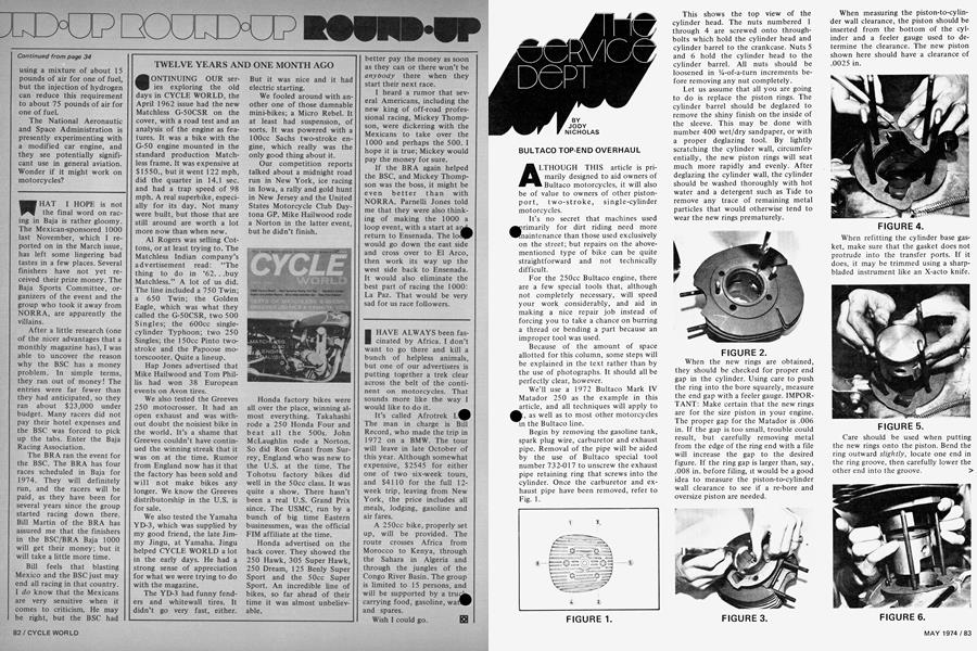
Begin by removing the gasoline tank, spark plug wire, carburetor and exhaust pipe. Removal of the pipe will be aided by the use of Bultaco special tool number 732-017 to unscrew the exhaust pipe retaining ring that screws into the cylinder. Once the carburetor and exhaust pipe have been removed, refer to Fig. 1.
This shows the top view of the cylinder head. The nuts numbered 1 through 4 are screwed onto throughbolts which hold the cylinder head and cylinder barrel to the crankcase. Nuts 5 and 6 hold the cylinder head to the cylinder barrel. All nuts should be loosened in %-of-a-turn increments before removing any nut completely.
Let us assume that all you are going to do is replace the piston rings. The cylinder barrel should be deglazed to remove the shiny finish on the inside of the sleeve. This may be done with number 400 wet/dry sandpaper, or with a proper deglazing tool. By lightly scratching the cylinder wall, circumferentially, the new piston rings will seat much more rapidly and evenly. After deglazing the cylinder wall, the cylinder should be washed thoroughly with hot water and a detergent such as Tide to remove any trace of remaining metal particles that would otherwise tend to wear the new rings prematurely.
When the• new rings are obtained, they should be checked for proper end gap in the cylinder. Using care to push the ring into the bore squarely, measure the end gap with a feeler gauge. IMPOR TANT: Make certain that the new rings are for the size piston in your engine. The proper gap for the Matador is .006 in. If the gap is too small, trouble could result, but carefully removing metal from the edge of the ring end with a file will increase the gap to the desired figure. If the ring gap is larger than, say, .008 in. before filing, it would be a good idea to measure the piston-to-cylinder wall clearance to see if a re-bore and oversize piston are needed.
When measuring the piston-to-cylin der wall clearance, the piston should be inserted from the bottom of the cyl inder and a feeler gauge used to de termine the clearance. The new piston shown here should have a clearance of .0025 in.
When refitting the cylinder base gas ket, make sure that the gasket does not protrude into the transfer ports. If it does, it may be trimmed using a sharp bladed instrument like an X-acto knife.
Care should be used when putting the new rings onto the piston. Bend the ring outward slightly, locate one end in the ring groove, then carefully lower the other end into the groove. )
Once the piston rings have been fitted to the piston, rotate them until the ring-locating pin is found in each ring groove, and make sure the ends of the ring fit on either side of this pin. Lightly oil the rings and piston using the two-cycle oil you will be using in the fuel/oil mix.
Start lowering the cylinder over the hold-down studs and tilt the barrel slightly so that one edge of the piston ring (preferably the edge away from the ring-locating pin), can be slipped into the lip at the bottom of the cylinder liner.
Working carefully, tilt the cylinder back and forth until both rings are inside and the cylinder can be pushed down onto the crankcase without resistance.
Carbon should be scraped from the combustion chamber and cylinder/cylinder head mating surfaces (see arrow) with a dull, rounded screwdriver or other suitable tool. Take care not to scrape or gouge the aluminum surfaces.
Please refer back to Fig. 1 for an understanding of the correct procedure for tightening the cylinder head. Place the head on the cylinder with the narrow portion facing the rear of the motorcycle. Replace the flat washers on the studs and screw the nuts down finger tight. Use a torque wrench and tighten the cylinder head nuts down, 2 lb.-ft. at a time, in the numbered sequence in Fig. 1. Continue tightening nuts 1 through 6 until you reach 1 1 lb.-ft. stop on nuts 5 and 6. Continue tightening the other 4 nuts until you reach 1 4 lb.-ft.
It may seem like a small point, but this tightening sequence assures that the cylinder is pulled down squarely against the crankcase, obviating the chance of piston seizure due to uneven tightening of the hold-down bolts, and subsequent tilting of the cylinder.
Replace the carburetor after cleaning it thoroughly with a suitable cleaning solvent and re-attach the exhaust pipe, using a new exhaust port gasket. If you do install a new piston, it would be advisable to run at least one tank of gas through the engine using new engine break-in procedures, and a slightly richer fuel/oil mixture.
After the engine has been run for a couple of hours, retighten the cylinder head nuts again and snug up the exhaust pipe fastening ring. Do this when the engine is cold. You should enjoy many hours of troublefree riding.
BMW DRIVESHAFT
I am not one who generally writes to editors, as I accept minor errors as something most of us are prone to commit. My appreciation for your magazine is expressed by my check at renewal time. When I am dissatisfied, my checks will quit coming. There is one point I would like to take exception to, as the error has been repeated several times.
In several articles about the BMW you have stated that the helical gear in the drive shaft mechanism allows for length changes in the drive shaft. Careful consideration and analysis would prove this statement in error. If you check, I believe you will find the splined coupling provides for growth or shrinking in normal use. The helical gear would have to be designed for a fixed position along the radius. A call to any reliable BMW mechanic or qualified technical individual at the distributor will verify or prove me wrong.
A quick check with a first year engineering student could be just as effective. Drawings in BMW handouts also seem to indicate that my assumption is correct. Perhaps your writers need some basic courses, but then I can appreciate their wish to ride rather than worry about how the bike is built.
To end this on a cheerful note, I must say that I like the magazine. Keep up the good work, and I’ll keep my checks coming. Although my interest lies in street bikes or touring, I usually read all of the articles.
Paul Marking Scottsdale, Ariz.
It is very comforting to know that our road tests are being thoroughly digested by a few of our readers, even though what we say may not always b¿ 100 percent correct. We work very ha^ to ensure that these tests are technically correct and personally unbiased, both of which are difficult jobs at times.
In the most recent BMW road test, which appeared in the Feb. ’74 issue of CYCLE WORLD, we did say “slight changes in the length of the driveshaft are compensated for by curved, helical teeth in an internally splined coupling shaft.” We were in error in that although the teeth are curved from their base towards the ends, they are not, technically speaking, helical gears.
A helical gear is a “toothed gear in which the wheel-teeth, instead of being at right angles with their faces, are set at some other angle therewith.” A spur gear, on the other hand, is “a toothed wheel whose teeth are on the outside diameter, and at right angles with the wheel face.”
At the rear of the drive shaft in all BMW motorcycles is a sliding, splined coupling that permits the shaft to change length as the rear wheel moves up and down. Just to the rear of this is the ring and pinion gear assembly, which is very similar to the one found in most automobiles. The sliding, splined coupling is made up of spur gears with an involute tooth form, and not a helical gear. Our mistake. Thanks for calling our attention to it.