How Motorcycles W·o·r·k 7
HOW motorcycles W·O·R·K 7
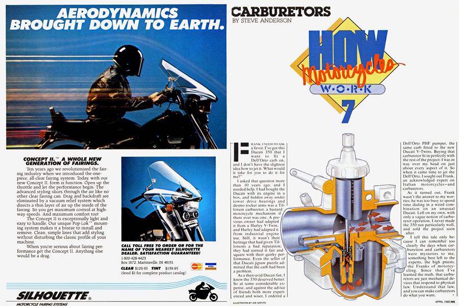
CARBURETORS
STEVE ANDERSON
FRANK, I NEED TO ASK a favor. I’ve got this Ducati 350 that I want to fit a Dell’Orto carb on, and I don't have the slightest idea how to jet it. What would it take for you to do it for me?”
I asked that question more than 10 years ago, and I needed help. I had bought the Ducati with its engine in a box, and hidden away under tower drive bearings and desmo rocker arms was a Tillotson carburetor, a bastard motorcycle mechanism if there ever was one. A previous owner had adapted it from a Harley V-Twin, and Harley had adapted it from industrial engine use. Still, it wasn’t their heritage that had given Tillotsons a bad reputation; they had earned it fair and square with their quirky performance. Even the seller of that Ducati jigsaw puzzle admitted that the carb had been a problem.
As a then-avid Ducati fan, I knew the 350 deserved better. So at some considerable expense, and against the advice of friends both more experienced and wiser, I ordered a DeirOrto PHF pumper, the same carb fitted to the new Ducati V-Twins. Buying that carburetor fit in perfectly with the rest of the project; I was in way over my head on just about every aspect of it. So when it came time to jet the DeirOrto, I sought out Frank, an acknowledged expert on Italian motorcycles—and carburetors.
As it turned out, Frank wasn’t the answer to my worries; he was too busy to spend time dialing in a weird combination on an unusual Ducati. Left on my own, with only a vague notion of carburetor operation, I never made the 350 run particularly well, and sold the project soon after.
I tell this tale only because I can remember too clearly the days when carburetion and carburetors were mysteries to me, something best left to the experts, the high priests, the Franks of motorcycling. Since then I’ve learned the truth, that carburetors are just mechanical devices that respond to physical law. Understand that law, and you can make carburetors do what you want. >
But the question is, what do you want carburetors to do? Well, for proper engine operation, only two functions are required. First, the carburetor must control the amount of power an engine makes. It does this by acting as an adjustable valve that controls the amount of air that can flow into the engine. Second, the carburetor must mix a precise amount of gasoline with this incoming air to produce an air/fuel mixture that the engine can burn.
This second requirement is the carburetor’s main task, and the more difficult of the two. The chemistry of combustion, at least on paper, dictates that for every l 5 pounds or so of air an engine takes in, one pound of fuel is required. In a real engine, however, that's seldom the exact air/ fuel ratio actually desired. Best power is made with a mixture richer in fuel; such a rich mixture ensures that every bit of oxygen in the air will find some gasoline to mate with during the brief period of combustion. Engine starting and idling also require a richer mixture, but best fuel economy is achieved with a leaner air/fuel mix than the chemically correct one. Most of these variations from the chemical ideal result because fuel and air aren’t mixed perfectly or consistently at all engine speeds. Figure I shows the mixture ratios that a carburetor should provide for a street-going four-stroke.
And it’s not enough that the carburetor simply provide the right amount of fuel; it must also provide that fuel in the proper form. Ideally, that would be gasoline vapor, but, more practically, all that can be expected is that a carburetor add the gasoline as very small droplets that will evaporate during their trip down the inlet tract into the cylinder.
So the two tasks that carburetors must perform are airflow control and gasoline addition. In this modern world of integrated circuits and electronic sensors, there assuredly are complicated answers to those needs. But carburetors predate electronic complexity, and instead depend on simple princples of fluid flow, on pressure balances and on precise hole sizes.
Air behaves in predictable ways, ways that a carburetor uses to accomplish its mission. In any situation in which there is steady flow, air pressure is directly related to air speed. As air speed increases, air pressure drops.
This fact is made use of in everything from airplanes to paint sprayers. The wings of an airplane create lift because the air flow over the top of a wing is faster than under the bottom, leading to lower pressures on the top than the bottom. The net effect of the competing pressures is a push upward. Paint spayers work because air is forced to accelerate down a small tube, and as it speeds up, it loses pressure. Branching out from the low-pressure area of the small tube is another tube that runs vertically down into a paint reservoir. The air above the reservoir is at atmospheric pressure, which is higher than the pressure in the small airflow tube, so the difference in pressure forces paint up through the vertical tube. The paint sprayer is simply a pump that operates from differences in air pressure created by air flow.
Fundamentally, a standard motorcycle carburetor works in the same way as a paint sprayer (see Fig. 2). Air rushes through the bore of the carburetor, causing the pressure in the bore to drop. A tube connects the carburetor bore to a reservoir of gasoline. Because the pressure is greater at the bottom of the tube than at the top, gasoline is pumped up the tube, into the carburetor bore where it mixes with the incoming air. The exact amount of gasoline pumped depends on the the pressure difference (known in carburetor parlance as the metering signal) and the resistance to fuel flow in the tube.
What we have just described is a carburetor in its rawest form. Of course, it’s only a conceptual carburetor, unsuitable for actual use. There still are problems that must be solved, particularly controlling the quantity of air drawn into the engine, and supplying the correct proportion of fuel for the amount of air that is flowing. The two factors that affect fuel flow are the pressure drop that powers gasoline movement, and the resistance to flow in the fuel tube. Establish those two with precision, and accurate fuel metering is possible.
The first step in controlling the pressure difference (the metering signal) is to stabilize the pressure at the bottom of the fuel tube. That requires the level of gasoline in the fuel reservoir to stay constant. Carb designers have borrowed from household plumbing in accomplishing this: The float and valve mechanism (see Fig. 3) that controls the level in the reservoir is a miniature version of the mechanism that controls the water level in a flush toilet. With a constant fluid level, and the air space above the gasoline vented to the atmosphere, the pressure at the bottom of the fuel tube will remain as constant as the ambient air pressure.
The second step in establishing the metering signal is controlling the air speed, and therefore its pressure, in the carburetor bore. The smaller the bore, the higher the air speed; the lower the pressure, the stronger the metering signal. But as air speed in the carburetor bore increases, frictional losses also increase, and it becomes more difficult to cram as much air through the intake system as the engine would like. To minimize intake losses, the trick is to have maximum air speed only where it does the most good. This can be done by necking down the carb bore right at the fuel supply tube. This constriction must carefully and gradually blend into the larger diameter of the bore on both sides, otherwise the sudden change in area would result in turbulence and subsequent flow losses. This type of constriction is called a venturi, a term that also has come to mean the smallest diameter anywhere in the carburetor bore, regardless of its shape.
At this point, the pressures that pump gasoline from the fuel reservoir are controlled as well as can be; the final step in regulating the mixture is to control the gasoline’s resistance to flow. That can be done by putting into the fuel tube a replaceable plug with a precisely sized hole in it, a part known as a jet.
This completes a carburetor (seeFig. 4) that would be suitable for use on an engine designed to run at a single speed, as in industrial use. The size of the venturi would limit the engine’s power output by limiting the maximum amount of air that can enter the engine, and the proper size jet would provide the desired fuel/air mixture.
Control of air flow (and thus engine power) comes from the addition of a throttle to the carburetor. A throttle is a mechanism that varies the area of the carburetor bore. (To be tediously precise, the twistgrip on the right handlebar end isn’t the throttle; it’s the throttle control.) One of the most common types is the butterfly throttle, a round plate that pivots inside the carburetor bore. At one extreme, the butterfly almost completely blocks the bore; this would be the minimum flow position, the one for engine idling. At the other extreme, the butterfly swings almost 90 degrees to be out of the airflow’s way, and maximum power is produced. An alternative to this is the slide throttle, which is a plug or guillotine that can project into the carburetor bore to block the air flow. The slide throttle is almost never used in automotive carburetors, but is very common on motorcycles.
Positioning of the throttle is vital because of the effects it has on air pressure. Upstream of the throttle, air presssure is affected only as much as the throttle causes air flow, and therefore, air speed, to change. With the throttle fully open, upstream air velocities are high, pressure low. With the throttle pari tal ly closed, upstream air flow slows down, and pressure rises. Right at the throttle (when it’s partially closed), air speed is very high and air pressure is low. And because of the sudden area change and associated tubulence, the entire area downstream of the throttle is subject to almost the same low pressure. >
Carburetor with butterfly throttle in place.
Consequently, if the throttle were upstream of the fuel tube, closing the throttle would reduce air flow while dropping the pressure over the fuel tube. In other words, it would increase the metering signal and gasoline flow just when it should be weakening them. If the throttle were downstream of the fuel tube, however, better things happen (see Fig. 5). When air flow drops, the air pressure over the fuel tube increases, and fuel flow drops. And at this point, at least, the fuel and air flow in our imaginary carburetor are behaving in generally the right way to preserve a constant fuel/air ratio.
But while the general direction is right, the details aren't.
The fuel/air ratio achieved with this single-jet carburetor at different throttle openings follows a curve as shown in Figure 6. Over much of the operating range, the fuel/air ratio stays relatively constant, becoming somewhat richer as the load increases. But at low loads, the mixture goes deadlean because the metering signal isn't strong enough to draw gasoline up out of the fuel tube. Thus, our single-jet carburetor will provide a mixture an engine can use only at higher power outputs; it won't allow an engine to idle.
Remedying this situation requires the addition of another fuel metering circuit. Essentially, this circuit is a miniature carburetor within the main carburetor body, and its sole function is to provide an idle mixture. It must be located in the carburetor bore at a point where the air velocity is high and the pressure low when the throttle is almost closed. And the area immediately under the throttle fits that description; so a second fuel tube connecting that area to the gasoline in the fuel reservoir can be used to supply gasoline for idle conditions. A small jet in this fuel tube meters the flow, and is called, appropriately enough.
an idle, or pilot, jet.
Because the pressure difference—the metering signal — across the idle circuit is very large, and because the fuel requirements at idle are very small, the hole in the idle jet would have to be incredibly tiny and difficult to manufacture. That's why most carburetors reduce the signal to some extent by bleeding air from the carb's intake mouth into the idle circuit. The air bleed is generally adjustable with a screw, so it also allows fine-tuning of the idle mixture without changing idle jets. The air bleed also helps to break the gasoline into a useful mist.
A carburetor with an idle circuit as described is shown in Figure 7. And remember that an idle circuit works backwards from the main circuit: When the throttle opens, air pressure increases over the idle circuit, and decreases over the main circuit. So the metering signal at the idle circuit drops as the throttle opens, and it supplies progressively less gasoline just as air flow through the carburetor approaches the point where the main circuit can start supplying gasoline. And if all the shapes, sizes and locations are right, the output of the idle circuit and the main circuit can add up as shown in Figure 8 into a mixture curve that allows a wide range of engine power outputs.
While the operational capability of our carburetor at this point is complete, it's far from the optimum. The mixture curve over the entire load range isn't as tailored as an engine might like (remember Figure I?)\ and at low loads, when velocity through the carburetor bore is low, the gasoline may dribble out in large droplets that don't mix well with the incoming air. Also, if the throttle is fully opened when the engine isn’t spinning quickly, the air velocity and metering signal over both the main and the idle circuits can drop so low that no fuel at all will be supplied.
The standard answer to those concerns on current street motorcycles is the constant-vacuum, or variableventuri. carburetor (see Figure 9). Basically, this is a butterfly-throttle carburetor modified to have a venturi area that is automatically adjusted so that the air velocity through the venturi remains constant. With velocity constant, pressure in the venturi remains constant as well, and therefore provides a constant metering signal. This means the amount of gasoline brought up the main fuel passage into the carburetor bore is no longer dependent on changes in the metering signal; instead, the mixture is controlled by varying the restriction in the fuel circuit.
All of this is accomplished with a cylindrical slide that moves up and down in the carburetor bore immediately over the main fuel circuit: as the slide drops, it progressively blocks more and more of the bore, locally decreasing the area available for air flow (see Figure 9 again). By varying the height of the slide, air speed and pressure can be kept constant in the venturi.
What’s clever about this design is that no cables or linkages attach to the slide; instead, the slide is free-floating, and its height is automatically controlled by the pressure in the venturi. The slide is shaped like an upside-down top hat; the area above the slide is vented to venturi pressure by a hole through the bottom of the slide, while the area under the slide's hat brim is vented to atmospheric pressure. The pressure differences tend to push the slide up, which increases the venturi area and thus allows the air under the slide to slow down, which, in turn, reduces the very pressure difference that caused the slide to rise in the first place. The slide will rise only until a balance is found between the pressure trying to push it up and the forces (its own weight, and the force of its return spring) trying to push it down. This balancing act ensures that the air pressure under the slide will remain constant during most of the carburetor's operating range. Most current street bikes use constant-velocity carburetors very similar to the one shown in Figure 9. But while they do provide precise fuel/> air mixtures and smooth operation, they aren't the only type of motorcycle carburetor. The long-standing alternative is the pure slidethrottle carburetor, still the mainstay of dirt bikes and racing machines. Slide-throttle carburetors are much like constant-velocity carburetors with the butterfly deleted, and with the slide placed under rider control to serve as the throttle (see Figure 11).
With a constant metering signal, the main jet would tend to flow' the same amount of gasoline at all times. So to prevent that, a second restriction to gasoline flow' is provided bv an additional jet (the needle jet) in the fuel tube, above the main jet. A tapered needle attached to the bottom of the slide projects into the needle jet (see Figure 10); and the amount of fuel that can flow through the tube at any given time depends on exactly how thick the needle is where it passes through the needle jet. And because the needle position depends on slide height, and because slide height depends on the amount of air flow, the restriction to fuel flow can always be exactly as required for the right fuel/air mixture.
Slide-throttle carbs act, however, more like an array of simple, unthrottled, fixedventuri carburetors of the type shown in Figure 4. It’s as though the rider carries along a large selection of fixed-venturi carburetors, each a different size, and must reach down and change carbs as he rides, selecting a large one for acceleration, and a small one— which would have a higher air speed and metering signal than a large one—for putting around town. This array of carburetors would perform in a fashion similar to that of a single fixed-venturi carburetor with a butterfly throttle, but with an important advantage: At low loads, the metering signal would be stronger, and gasoline entering the bore would be better mixed.
With a rider-controlled slide, the needle and needle jet vary the fuel restriction as the venturi size changes, just as they do on a constant-vacuum carb. And as with the fixed-venturi carburetor, air speed at any given slide height increases as engine speeds go up, which increases the metering signal and fuel flow, if in a slightly richer than desirable fashion.
At very low air-flow rates, the slide-throttle carburetor runs into the same problem as other carbs: The metering signal can be too weak to pull fuel up through the main fuel circuit. So, just as on other of carbs, the solution on a slidethrottle type is a separate idle circuit. Once again, the idle circuit is placed where it will be subject to the lowest pressure in the carburetor bore when the throttle is almost closed: right under the front of the slide, where air velocity is highest with the slide down. As the slide is raised and over-> all air flow through the carburetor rises, the pressure increases at the idle fuel discharge and decreases at the main fuel discharge.
Exactly how this transition occurs between the idle and main fuel circuits is affected by how much higher the bottom edge of the slide is on its upstream side than on its downstream side—a difference known as the slide cutaway. The lower the rear edge of the slide, the further forward incoming air is accelerated, and so the lower the pressure over the main fuel circuit at small throttle openings. With little cutaway, the main and idle circuits are exposed to very similar pressures at all times, and the mixture at small throttle openings is richer. More cutaway delays the main-circuit operation until the slide rises higher, so there’s less difference in air velocity over the main and idle circuit. As the slide rises higher yet, the velocities and pressures over the two circuits tend to even out, and the main circuit takes over.
Once that happens, fuel flow is controlled only by the the restrictions in the main fuel tube. At intermediate openings, that’s the needle and needle jet. At full throttle, with the slide fully open, the area between the needle and needle jet is bigger than the area of the main-jet hole, and so only the main jet controls gasoline flow and mixture strength.
The advantage of a slidethrottle carburetor over a non-constant-velocity butterfly carb is that air velocity and the metering signal at part throttle operation are generally higher, leading to smaller gasoline-droplet size and better mixing. But as with most simple carburetors, the mixture tends to riehen for any given throttle setting as engine speed and air flow increase. A common correction for that is an air bleed into the main fuel circuit as shown in Figure 12. The air bleed tends to compensate for the the progressive enrichment at higher air flows, and also serves to better mix the gasoline and decrease droplet size. The larger the air bleed, the more the effect.
continued on page 106
continued from page 102
One condition that slidethrottle carburetors won't tolerate is the quick opening of the throttle at low' engine speeds. That leads to low air velocities over both the main and idle circuits, causing an overly lean mixture and a sag in power that can make the engine stop running altogether. Because the likelihood of this happening increases as venturi size increases, and because the same condition can't occur with a constant-vacuum carburetor. slide-throttle carbs often have to be smaller than constant-vacuum carbs for streetbike use. And even then, they sometimes need the assistance of an accelerator pump So contrary to popular opinion, constant-vacuum carburetors may be the best for street performance.
In the case of either carburetor type, tuning involves using the right individual components in each carb circuit to supply the right mixture. Figure /3 shows which components affect the mixture at' any given throttle position for a typical slide-throttle carburetor. Constant-vacuum carbs behave similarly, but with the added complexity of having the active circuit dependent on both throttle position and' slide height. But in either case, if you know whether the mixture is rich or lean at a particular operating condition. the fix is to change only the carburetor component that affects the mixture under, that condition.
That's why understanding carburetor operation is just the necessary first step to a complete mastery of carburetor tuning. For just as important is the ability to read the air/fuel ratio supplied to an engine from the traces left on the sparkplug insulators and from the clues given by throttle response and exhaust note. When you combine that with the knowledge of what goes inside the hidden passages of a carburetor, the experts, the high priests of motorcycling, the Franks, won't have anything up on you. E3