Yamaha Yz250l Engine Hop-Up
YAMAHA YZ250L ENGINE HOP-UP
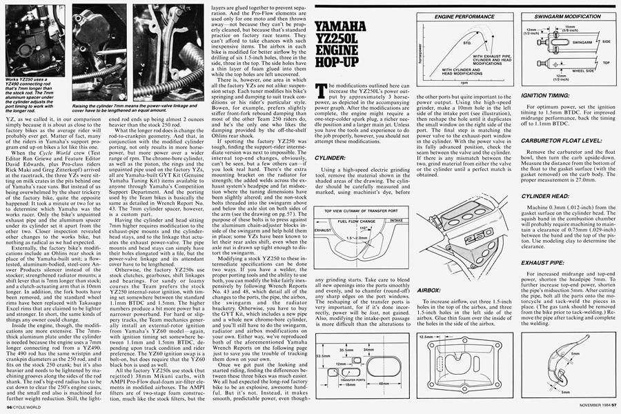
The modifications outlined here can increase the YZ250L’s power output by approximately 3 horsepower, as depicted in the accompanying power graph. After the modifications are complete, the engine might require a one-step-colder spark plug, a richer needle position and a larger main jet. Unless you have the tools and experience to do the job properly, however, you should not attempt these modifications.
CYLINDER:
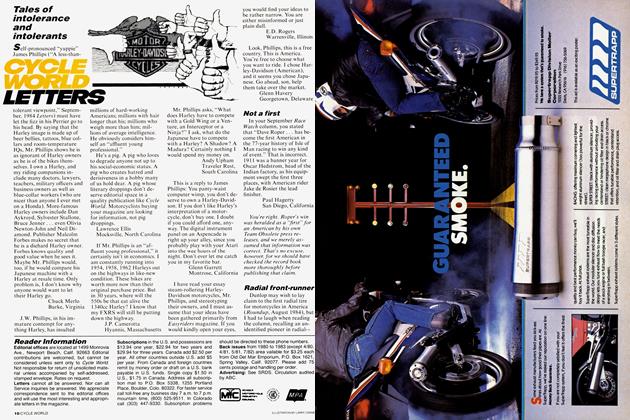
Using a high-speed electric grinding tool, remove the material shown in the shaded areas of the drawing. The cylinder should be carefully measured and marked, using machinist’s dye, before
any grinding starts. Take care to blend all new openings into the ports smoothly and evenly, and to chamfer (round-off) any sharp edges on the port windows. The reshaping of the transfer ports is very important, for if it’s done incorrectly, power will be lost, not gained. Also, modifying the intake-port passage is more difficult than the alterations to
the other ports but quite important to the power output. Using the high-speed grinder, make a 10mm hole in the left side of the intake port (see illustration), then reshape the hole until it duplicates the small window on the right side of the port. The final step is matching the power valve to the exhaust-port window in the cylinder. With the power valve in its fully advanced position, check the seam between the valve and the cylinder. If there is any mismatch between the two, grind material from either the valve or the cylinder until a perfect match is obtained.
AIRBOX:
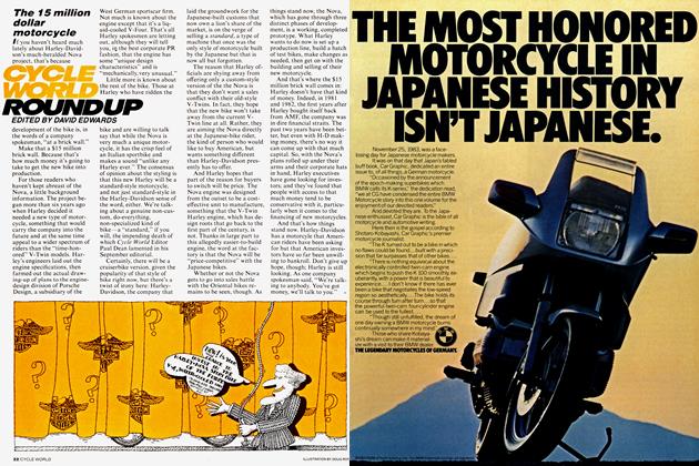
To increase airflow, cut three 1.5-inch holes in the top of the airbox, and three 1.5-inch holes in the left side of the airbox. Glue thin foam over the inside of the holes in the side of the airbox.
IGNITION TIMING:
For optimum power, set the ignition timing to 1.5mm BTDC. For improved midrange performance, back the timing off to 1.1mm BTDC.
CARBURETOR FLOAT LEVEL:
Remove the carburetor and the float bowl, then turn the carb upside-down. Measure the distance from the bottom of the float to the gasket surface (with the gasket removed) on the carb body. The proper measurement is 27.0mm.
CYLINDER HEAD:
Machine 0.3mm (.012-inch) from the gasket surface on the cylinder head. The squish band in the combustion chamber will probably require machining to maintain a clearance of 0.75mm (.029-inch) between the band and the top of the piston. Use modeling clay to determine the clearance.
EXHAUST PIPE:
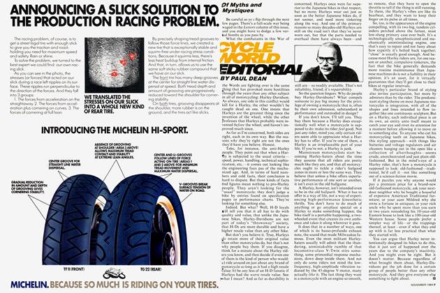
For increased midrange and top-end power, shorten the headpipe 5mm. To further increase top-end power, shorten the pipe’s midsection 5mm. After cutting the pipe, bolt all the parts onto the motorcycle and tack-weld the pieces in place. (The gas tank should be removed from the bike prior to tack-welding.) Remove the pipe after tacking and complete the welding.

More From This Issue
-
 Cycle World Editorial
Of Myths And Mystiques
November 1984 -
 Cycle World Letters
Cycle World Letters
November 1984 -
 Cycle World Roundup
The 15 Million Dollar Motorcycle
November 1984 -
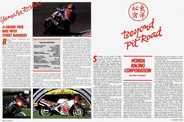 Special Section
Beyond Pit Road
November 1984 -
 Special Section
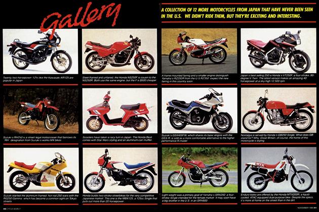
Gallery
November 1984 -
 Special Section
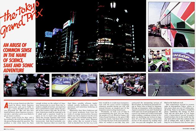
The Tokyo Grand Prix
November 1984
