Balancing the Mighty Multi
Balancing The mighty Multi
How To Build And Interpret Readings From A Carburetor Balancing Device (Using The Honda Four As An Example).
MATT COULSON
GARY PETERS
WITH THE INTRODUCTION of the mighty multi-cylindered engines on today's motorcycles, the problem of carburetor synchronization and manifold balancing becomes acute. It is especially noticeable on Honda's big Four, where a slight maladjustment can cause a great deal of lost horsepower. Unbalanced conditions in today's superperformers can cause problems as slight as a loss of performance or as great as burnt valves, pistons, and pipes. The lost performance is not always noticed, but the yellow to black exhaust pipes are never missed. Most conspicuous is the rather typical Honda Four coming into the dealership with only a few miles registered on the odometer and one of the beautiful chrome exhaust pipes turned a dull shade of blue-black. Such problems can usually be easily traced to an unbalanced condition causing a very lean and hot mixture in one or more cylinders. Dealers and do-it-yourselfers everywhere are trying to help the situation by using a number of available devices.
One such device is a simple velometer which fits over each carburetor throat individually. Another is a vacuum gauge, or a combination of vacuum gauges, which may hook to either the intake manifold itself or at the face of the carburetor, as does the velometer. Of course, the simplest device is nothing, and this method incorporates the removing of spark plug wires and tuning one cylinder at a time. Although this method is sometimes employed on Twins, it just doesn't work on the big Fours.
At the outset, when the first 750 Honda rolled into our garage, we devised a simple flow-meter device (like the Unisyn), which we used for many months with some degree of success. At least we could come close enough to avoid burned exhaust valves and pipes; however, the unit had to be switched back and forth between carbs, and this impaired normal engine operation on each application. Realizing that we were getting a less than perfect adjustment, something more accurate was desired.
We were confident that a set of four vacuum gauges would end all our problems and that the gauges would be the ultimate in perfection for making the fine adjustments we were demanding. The gauges were not as good as we had hoped, since oscillating needles, restrictor valves, stiff hoses, and needle dampers seemed to add too many variables, take too much time, and always caused difficulties in reading pressures accurately.
There was certainly something missing in all these devices, and realizing that nothing available looked like the real answer, we decided to try and develop something ourselves. The basic engineering principle and approach came to us quickly, but development and perfection was slow. Finally, after much trial and error, we feel we have devised a balancing instrument that really does the job. The unit plugs right into the Honda Four, is adaptable to all multis with individual carburetion and manifolding, and displays the performance of each cylinder accurately, in terms stated in shop manuals, without detrimental oscillations. Not only does it give an instant picture of all four cylinders at idle, but when the throttle is cranked, individual cylinder performance can be compared over the entire rpm spectrum. This instrument allows the operator to completely synchronize and balance the carburetion system, and it also can be used to troubleshoot other related problems. We have found it capable of noting the following conditions: leaky valves, sticking valves, weak or broken valve springs, worn valve guides, piston ring defects, blown cylinder gaskets, intake manifold leaks, restricted exhaust systems, and loose spark plugs (common on 750s). We call this instrument our Multi-Balancer.
THE MULTI-BALANCER
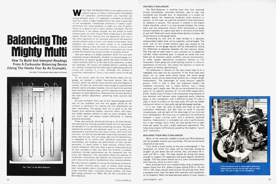
The Multi-Balancer is nothing more than four balanced U-tube manometers, mounted vertically, side by side, and numbered one through four. A manometer is a simple yet reliable device for measuring moderate static pressure or vacuum. In this case, we used the standard U-tube manometer to measure a vacuum. The vacuum is created in the engine intake manifold, which is an area located between the intake valve and the carburetor venturi. Each manometer or gauge consists basically of a glass tube bent in the form of the letter U and half filled with some liquid whose density is known. We chose mercury as the gauge liquid.
Connecting to one end of each U-tube is a specially compounded rubber hose, cut to a specific, critical length. The other end of the U-tube remains open and vented to the atmosphere, so the gauge vacuum will be indicated by noting the difference in elevation between the two mercury levels. The free end of each hose in turn connects to its respective cylinder intake manifold port. It should be noted here that there are no restrictor valves, mufflers, vacuum accumulators, or other system operational retardation devices on this instrument. Each gauge will yield readings directly in inches or centimeters of mercury. This allows the operator to easily set the engine to factory specifications.
The difference in density of the two uneven legs of air is negligible and need not be corrected. If the fluid used were water, oil, or some other dense liquid, the actual gauge pressure could not be determined directly by a simple length measurement. The advantages of using mercury (specific gravity, 13.6) is that it does not evaporate readily, has moderate sensitivity, has a stable density, has a sharp meniscus, and is easily seen. We do not recommend the use of water or oil (specific gravities of 1.0 and 0.83 respectively). Either would cause U-tubes to be excessively long because of low densities and because water evaporates easily, dissolves gases, is very transparent, and is difficult to read. If a dye is used, it tends to collect on the tube walls. Oil will rot rubber tubing and remain on tube walls, giving false gauge readings.
It is our hope not only to show you how to use this instrument effectively, but also how to build it yourself inexpensively, and yet gain all the advantages of our trial and error development. We want you to experience the difference between a good running multi and a perfectly balanced machine. Improvement is noticeable not only in performance, but in gas mileage; many times we have gained five to eight miles per gallon by only a slight carburetor adjustment. This helps show engine inefficiencies caused by that slightly "out of sync" carburetor.
BUILDING YOUR MULTI-BALANCER
Many of the materials needed to build your Multi-Balancer will be available around your workshop. The rest can be easily obtained at low costs.
First, build a stand similar to the one in photograph 1. The faceboard, on which the tubes will be mounted, should be straight up and down (do not incline), flat, and about 18 in. wide and 36 in. high. The base should be strong and heavy enough to support the apparatus and guard against accidental tippage. The face board should be of a color contrasting best with mercury, which is a silver color.
Next, purchase from your nearest hobby shop or laboratory supply house four 6-ft. pieces of glass tubing 5/32 in. ID and 1/4 in. OD. Glass should retail around 10 cents per foot. With a propane torch, heat the glass tube carefully and completely at its midpoint. When the glass becomes plastic in state, slowly > bend it into a U-shape, trying to maintain 2 in. parallel center to center and a clean 1-in. radius turn at the bottom. After all four tubes are bent properly, center them on the faceboard and mark their positions. They should all be straight up and down and parallel to each other. Allow the tops of the glass tubes to protrude 1 in. past the top of the faceboard, as this makes the hose connections easier. Glass tubes may be mounted by drilling a number of small holes in the faceboard and inserting soft copper wires around each tube, through the holes, and finally secured by twisting the wires gently together behind the faceboard. Scale lines can be drawn straight across the front of the faceboard in inch or centimeter increments, or individual scales of either type can be mounted next to each tube.
With the tubes mounted, fill them with mercury, which can be obtained at a laboratory or chemical supply depot, to the centerline or zero level (halfway point). Less than 1/2 fl. oz. of mercury should be adequate to fill all four of the tubes sufficiently. When filling, care should be exercised to avoid spillage and air pockets. Remember, when the filling is complete and the instrument is level, all columns of mercury should be equal and at the zero point. The heart of the Multi-Balancer is now complete.
Next, purchase 36 ft. of surgical rubber, 1 /4-in. ID tubing. (The length and type of hose used is extremely critical, as it affords the necessary damping qualities required without impairing accuracy or quick gauge response. The relatively long length and soft composition of the hose makes handling and hook-up a pleasant task.) Cut this tubing in four 9-ft. pieces. Carefully, push one end of each hose length over one protruding end of the four U-tubes. Each U-tube should still have one end open and free to vent to the atmosphere. Now the loose hose ends should be numbered to their respective gauges. Electrician's stick-on numbers are good for this purpose.
The final item necessary to complete your Multi-Balancer is the adapter, which is the final connection between the hose ends and the provided manifold test ports. As you can see in the photo, we elected to machine our own adaptors. Machining the connections is not a difficult task. Note the long extensions which make the two center carburetors easy to reach. If, however, you do not want to make your own, very nice adaptors are available from your local Honda dealer under the following numbers. Two of each of the following are required: Honda number 07068-30007 and Honda number 07068-30012. These adaptors are to be fitted to the loose hose ends, placing the extender attachments to the inner gauge hoses 2 and 3, and the short attachments to the inner gauge hose ends 1 and 4. If you are building the balancer for a Twin, Triple, or a Four other than the 750 Honda, drill and tap your intake manifolds at an accessible location between the carburetor venturi and the intake valve, using a convenient thread size and type. Then make adaptors to suit and manifold plugs to accommodate these holes. You are now ready to use your Multi-Balancer.
HOW TO USE YOUR MULTI-BALANCER
First, take the bike for a short run to get the engine up to operating temperature. Next remove the gas tank rear tail from its rubber mount and raise the tank about 3 in., inserting a small object to hold it in this upper position. This affords much more work space over the carbs where the adjustments will be made. Now mount your Multi-Balancer directly in front of your bike, raised to at least handlebar height so you can read it easily from both sides of the engine. Next, remove the manifold access screws and insert the proper adaptor and hose assembly to each carburetor. We suggest that a small fan be placed in front of the engine and used during the test to keep engine temperatures normal until skill is developed in using and understanding balancing techniques. After balancing two or three times, a complete balancing job should take only a very short time and a fan will not be required. Now, raise all four rubber boots from their throttle cable adjusters, exposing the adjuster nuts. Note that all the vacuum hoses are away from hot engine parts and exhaust pipes. We recommend that each hose be wrapped loosely around the handlebars to keep it up and out of the way. Watch that the hoses do not become kinked or pihched, which could affect the accuracy of your readings. Also, the choke must be completely off during all tests.
After all this preliminary work has been completed, start the engine. Allow the engine to idle for a few seconds to gain its equilibrium. Note that all outer cable casings are firmly seated in the adjusters on the carburetors. This is a common problem and should be checked several times during balancing operations. Note the mercury level readings on all four cylinders. Look for 20 to 22cm of mercury at idle. Using the idle adjustment screws, bring all mercury levels equal. Usually one or two will be slightly off. Note the rpm. We recommend idle to be set at 1000 rpm, even though the manual states that 850 to 950 is best. If idle rpm is too low or too high, adjust all idle screws in or out, keeping mercury levels equal in all four tubes.
Next, adjust the idle air screw by turning it in very small increments, within 1/8 turn in each direction, waiting every time for several seconds to locate the point of highest engine rpm shown on the tachometer. Perform this adjustment to all carburetors. Disregard any higher level of idle rpm gained by this adjustment.
Now open the throttle briskly, not exceeding 3000 rpm. Note if any mercury levels nosedive prior to their rapid climb. This symptom indicates that a premature or late slide opening exists, and the condition should be corrected automatically later. Maintaining 3000 rpm, note mercury levels. If one or more are not equal in column height, an adjustment must be made at the throttle cable adjuster located at the top of the carburetor. Allow the engine to return to idle and loosen the lock nut on the carb in question. Turning the adjuster nut counterclockwise will raise the mercury column, and turning clockwise will lower the column. Make each adjustment small, returning the engine to 3000 rpm to check the progress of each change. After a perfect balance is obtained on all four carbs, quickly check for balance at several other randomly selected rpms. If all systems are working properly, the mercury columns should stay equal at any rpm selected. Now recheck the idle for balance and proper rpm. Readjust if necessary. Check idle breakaway again; that also should have been corrected, and all columns of mercury should climb equally without nosediving.
As mentioned before, the instrument may pick up symptoms indicating other problems which must be solved before a good synchronization and balance can be obtained. Some of the common symptoms are:
Uneven cable pulls or sticky carb slides show up vividly, as the engine will balance at any given rpm, but will not remain balanced when the rpm is changed. Slides must be checked for free movement, and the cable for free play. You will learn to recognize these symptoms quickly and easily.
If a valve is leaking, the mercury will drop 3 to 17cm at regular intervals whenever the defective valve attempts to close.
A sticky valve will be indicated by a rapid, intermittent drop each time the valve is supposed to close. This is more evident when the engine is idling.
If there are any air leaks in the intake manifold, the mercury will naturally be way below the recommended 20cm of mercury, but will remain steady. Check for loose clamps on the carburetor connecting tube, which is a common problem.
If the indicated pressure at idle is ever less than 15cm of mercury, check for absence of slack in the throttle cable or a loose spark plug.
The preceding are some of the more common trouble symptoms we have run across. You will soon learn to recognize these and many more as you familiarize yourself with the operation of this instrument.
We certainly do not want to imply that the Multi-Balancer is a cure-all. However, combine it with a good timing light, feeler gauges, a good set of metric tools, and a little experience, and you can do a first class job of tuning today's mighty-multis.