The Service Department
THE SERVICE DEPARTMENT
JOHN DUNN
DIFFERENCE:1
Having been bitten by the trials bug this season, I plan to switch to a “pure” trials mount for next season. My choice has been made a good deal less difficult by studying CW Road Tests, but two questions still remain.
If motorcycle A has, for example, a first gear of 30.0:1 (overall to one); motorcycle B has a first gear of 25. 7:1 (overall to one); motorcycle C a first gear of 9.73:1 (overall to one); and motorcycle D a first gear of 21.7:1 (internal to one); how can motorcycle C be competitive with what seems to be a very high (and unsuited to trials) gear ratio? Secondly, what is the difference, if any, between overall: 1 and internal: 1 ?
Jeffrey Barr Wollaston, Mass.
I would assume from the contents of your letter, Jeff, that the type of trial you are referring to is the English “one day” observed trial. Choice of first and second gear ratios are of great importance, as the other gears are used only between sections or for normal street use. Some trials gearboxes have very low first and second gear, suitable for trails use, and normally spaced third and fourth gears suitable for street riding. The best first gear suitable for trials will depend, to some great extent, on the torque characteristics of the engine. A high torque large Single will pull a taller gear than its smaller, higher revving counterpart.
Your example C appears to be highly geared, even for a large high torque plonker. The final choice of ratio should be such that it will allow the machine to be ridden feet up at a snail’s pace, provide good snap response when the demand arises, and be high enough to cover a fairly slow section without the need to change gear midway through. Some of the longer varying speed sections will require a change to second on occasion. A close first and second gear are of advantage on these occasions.
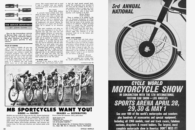
Overall gear ratio means exactly what it says. It is the overall ratio between the engine output drive shaft and the rear wheel axle and includes the primary drive ratio (between engine and gearbox), the gearbox internal ratio (the ratio inside the gearbox), and the final drive ratio (between the gearbox and rear wheel). The internal ratio is the ratio in the gearbox only.
Here’s an example: Primary drive, engine sprocket, 21 teeth; clutch sprocket, 45 teeth; 45/21 equals 2.12:1. Internal gearbox bottom gear ratio equals 2.3:1. Final drive, gearbox sprocket, 18 teeth; rear wheel, 58 teeth; 58/18 equals 3.22 to 1. Therefore, the overall ratio for bottom gear is 2.12 x 2.3 x 3.22, or 15.6:1.
THE TEN-BUCK CUB
Some time ago I purchased a Triumph Tiger Cub frame with wheels, good tires, tank, most of the engine, and so forth, from an old guy whose son used to ride it. It didn’t sound too bad for $10, so I bought it. I was surprised to find the engine (though missing most of the vital parts) had a high-lift camshaft, alloy lifters, Joe Hunt magneto, a reworked head for larger carburetor for this model, and the larger carburetor itself, which has a remote floatchamber. In the bottom of the box of parts I also found a shattered high compression piston, which could be the answer to the missing valve assembly, engine case and cracked cylinder.
With all the little racing goodies, I decided to buy another engine for the missing parts and build it up. In addition to the other engine, I bought new clutch plates, a roller-bearing rod kit, an oversized intake valve, and had a new crankshaft bearing made. The engine cylinder I bought was bored out 0.040 in., and the oversized piston has about an 8:1 compression ratio. I have the engine back together except for a cracked intake valve seat that has to be put in.
(Continued on page 10)
Continued from page 8
Do you think I should use a higher compression piston? Should I have high-tension valve springs, or are the stock springs adequate? Can you suggest any other modifications? How can I time it? What should I torque the head down to? What spark plug would be best suited? What fuel should I burn? These questions could go on forever, so if you just answer these and give any other hints it will be appreciated.
Allan A. Book Downey, Calif.
From the contents of your letter, Allan, you appear to know what you are doing. The purchase of the roller bear ing big end kit is a very worthwhile investment. I would suggest that you stick with the 8:1 compression ratio for the time being. It is one full ratio higher than standard, and should perform very well until you have had time to fully evaluate the performance of the high lift cam and larger bore induction system. It is not good practice to make several major changes to start.
However, make sure there is adequate valve-to-piston clearance with the high lift cam and the oversized piston. Both the intake and exhaust valve will come closest to the piston at sometime during the "overlap" period. In most cases the intake valve will be closest to the piston just before tdc, and the exhaust will be closest just after tdc. There are two basic methods used for checking valveto-piston clearance. The "clay impres sion" method is the most advisable when a new piston crown configuration is bemg employed for the first time. It shows clearly the clearance between the underside of the valve head and the bottom of the valve relief in the piston crown. Also, just as important, it shows the clearance between the outer edge of the valve head and the edge of the valve relief pocket. To check valve-to-piston clearance in this manner it will be necessary to fill the valve relief pockets in the piston crown with modeling clay, assemble the engine, and set the valve lash to the normal operating clearance, then turn the crank over several times slowly to obtain a good impression in the clay.
An alternative method of checking the valve-to-piston clearance can be achieved by compressing the valve (pushing the valve down until it touches the piston) at intervals of 3 to 5 degrees of crankshaft rotation during the over lap period. Using a dial indicator, with the point registering on the top valve spring retainer, will give actual valve movement and therefore clearance be fore the valve touches the piston. It will be necessary to devise a positive method of compressing the valve. A lever that holds and actuates the rocker arm is the most used method. -
Proceed to - check the valve-to-piston clearance in the following manner: Starting with the intake, turn the crank in the normal direction of rotation until 20 degrees btdc, set the dial indicator to 0, then compress the valve until it touches the piston. The clearance will be the same as the indicated travel on the dial. Repeat this procedure every 3 degrees until approximately 10 degrees atdc, reseting the dial to zero at each new position of the crank. The exhaust can be checked in the same manner, starting 10 degrees btdc and finishing 30 degrees atdc. On a hemispherical ohv or ohc engine it will be necessary to remove one of the pushrods or rocker arms to insure that the valves don't tangle when one is being compressed. The advantage with this method is that the engine does not have to be dis mantled to check valve-to-piston clear ance.
On your particular engine, treat 0.075 in. as minimum valve-to-piston clearance. Not knowing the type or make of the high lift camshaft you are using, it is difficult for me to advise on the suitability of the standard valve springs. If you know the type and make of the cam, contact the manufacturer and get his advice on the most suitable valve spring, including what the best set height is for good control throughout the intended speed range. Also, find out what the recommended timing is. If you cannot identify the make of the cam shaft, it will first be necessary to as semble the engine and check what maximum lift is at the valve. Dismantle cylinder head and check distance between the bottom valve spring seat and the top retainer for both inner and outer springs. This is known as set height. Now check the coil bound height (fully compressed length) of both springs. You now know the set height and how much farther the springs are compressed when the valve is on full lift, so make sure the springs do not become closer than 0.080 in. from coil bind when the valve is on full lift. If all is in order, assemble the valve and spring assembly with the lowest possible seat pressure. If the engine maintains good valve control throughout the normal speed range, there is nothing to worry about. However, if loss of valve control is experienced, it will be necessary to increase the spring pressure. To achieve this, place steel shims under the bottom spring retainer in 0.010-in. increments until the desired effect is achieved, bearing in mind the limitations previously mentioned regarding adequate clearance before coil bind. If you have no information with respect to correct valve timing, it is best to start with the intake and exhaust opening and closing points split equally either side of tdc on the overlap period. Example, intake opens 50 btdc and exhaust closes 50 atdc. You can always experiment by advancing or retarding the cam 2-3 degrees afterward to find the optimum position. With each change always check that you have adequate valve-to-piston clearance. Start with a KLG F 80 or equivalent spark plug and premium gasoline. [o]
(Continued on page 14)
Continued from page 10