Valves And Porting
VALVES AND PORTING
GORDON H. JENNINGS
SURELY, there is nothing in this world so near the heart of the do-it-yourself speed-tuning artist as the subject of valves and porting - and the ways in which these can be altered to improve engine performance. This preoccupation with the engine's ventilation apparatus is understandable, however, as the ultimate power potential of any engine depends, in large measure, on how efficiently it draws air in, and pushes the exhaust products out. The piston-type, internal combustion en gine is a wondrous and complicated device but strip ped of all its mystery, it emerges as an air-pump, pri marily, and the only things that make it work better are those that increase the flow of air. Decreases in internal friction will help, naturally, and so will an increased compression ratio, but there are sharp limits to what may be accomplished in those categories and in the end we are left with the task of improving the rate of air flow.
To that end there have been many schemes tried: supercharging is the most direct and generally the most effective method, but it carries with it some severe me chanical and economic penalties. Whether or not the engine is designed specifically for forced induction, there is always a lot of additional, power-consuming and heavy machinery to be heaped around the engine, and as this machinery must be precision-made, it is expensive. Moreover, in competition there are always rules to penal ize and sometimes even to forbid, supercharged engines; all of which tends to minimize their advantage. In the tour ing motorcycle field, it is usu ally less expensive and much less complicated to simply in crease the piston displacement - and that accomplishes the same thing as the supercharg er. A greater volume of air is moved through the engine, per unit of time, and as a natural consequence the engine devel ops more power.
Discounting supercharging, we are left with atmospheric pressure, which is approximately 14.7 pounds per square inch at sea level. Limited to this, it behooves us well to make good use of this induction pressure - and that means that we must hold induction and exhaust system flow resistance to a minimum.
There have been some extremely interesting experi ments made in trying to provide the best air flow. To day, the poppet valve is just about the only thing being used, but it was not always so. The most prominent competitor for the poppet valve was the sleeve valve, which as some of you may recall was a feature in the Willys-Knight automobile. There are, basically, two dis tinct types of sleeve-valve systems: The first was the double sleeve type, in which a pair of thin metal sleeves, one inside the other, moved up and down in the cylinder, covering and uncovering ports located at the top of the bore. This worked well enough, but it was difficult to keep the sleeves lubricated without losing a great deal of oil out the ports, and if the oil supply was restricted, rapid wear followed. In any case, the sleeves had the unfortunate characteristic of isolating the piston from the relatively-cool cylinder wall and the thermal overload that resulted from this made piston and ring life rather short in most instances.
A later, and much more satisfactory arrangement, was the single-sleeve valve system. Here, there was only the one sleeve, which brought the piston much. nearer the cooling water, and the valving action was provided by moving up and down, and rotating it at the same time. The actual admission of intake-air, and the release of the exhaust was, once again, through the matching and unmatching of ports at the top of the bore. Needless to say, when the ports in a sleeve-vIIlve engine were open, they were really open, and the power and broad-range torque of the single-sleeve valve engine gave this type of engine a lot of promise. The reason the type is no longer seen today is not altogether clear. There were difficulties encountered with the sleeve bulg ing out into the ports under high gas pressures, and the mechanism that drove the sliding, oscillating sleeve was a designer's nightmare, but the power was certainly there. Someday, we might see a revival of this type.
Less promising, in the opinion of the people who are supposed to know, are the other substitutes for the pop pet valve, such as the rotary valve. This type usually takes one of two shapes: it will be a conical rotor, set into the top of the cylinder, or a ported tube, rotating at a `right angle to the cylinder axis. Both of these have been tried many times, in one variation or another, but they always fail due to the cooling, sealing, and lubri catin2 rroblems created by the basic configuration.
These things are interesting alternatives to the pop pet valve, and they make good conversation, but in the end it will be more profitable, particularly for the amateur with limited resources, to stick closely to convention -and that means the poppet valve. There is plenty yet to be done, even by the individ ual tuner, if the task is un dertaken with a thorough knowledge of the subject.
The ordinary poppet valve, however popular it may be with engine designers, is a dreadfully poor device from the standpoint of getting the engine's working gases in and out of the cylinder, it is set right across the main line of airflow, and even when jammed open to the maximum it still represepts a seri ous obstacle to flow. Even so, it does provide a reliable seal, when closed, and it can withstand for long periods the high thermal and mechanical stresses imposed on it by high-speed, high-output operation. That is, in a nut shell, the reason we are stuck with it, and we simply must learn to live with its shortcomings. One of the best means of making the poppet valve do the job is to make it big-and that is precisely what is done: Unfortunately, there are limits on the size of valve that may be fitted into any given cylinder.
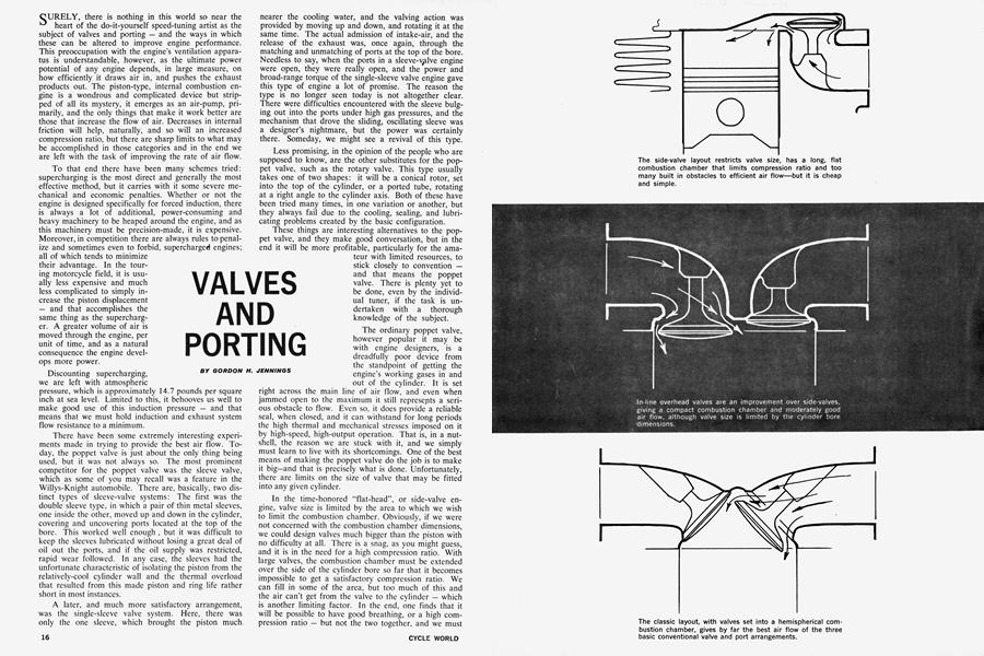
In the time-honored "flat-head", or side-valve en gine, valve size is limited by the area to which we wish to limit the combustion chamber. Obviously, if we were not concerned with the combustion chamber dimensions, we could design valves much bigger than the piston with no difficulty at all. There is a snag, as you might guess, and it is in the need for a high compression ratio. With large valves, the combustion chamber must be extended over the side of the cylinder bore so far that it becomes impossible to get a satisfactory compression ratio. We can fill in some of the area, but too much of this and the air can't get from the valve to the cylinder - which is another limiting factor. In the end, one finds that it will be possible to have good breathing, or a high com pression ratio - but not the two together, and we must have both if really satisfactory specific power outputs are to be obtained. For that single reason, the flat-head is rapidly disappearing from the scene. There are other reasons, such as the extreme difficulty of cooling the area between the valve seat and the cylinder, and all around the exhaust port, but these may be overcome to some extent. No amount of cleverness will get us by the fundamental unsuitability of the flat-head for really efficient, high-output operation.
The first step upward from the flat-head is to a simple overhead valve configuration, with the valves parallel to each other and more or less parallel to the cylinder bore axis. This arrangement is common in automobile engines and has several things to recommend it. This arrangement gives a good, compact combustion chamber and smooth running, and has the very real advantage of being cheap to manufacture. Indeed, where the basic valve system must be repeated for, say, eight cylinders, there is very little choice. The complexities entailed in operating valves set at wide angles in hemispherical combustion chambers are more than the automotive engineer wants to face.
The engineers who design motorcycle engines are made of braver stuff, and there is hardly a single fourcycle motorcycle engine being manufactured today that does not have inclined valves and hemispherical combustion chambers. Despite all of the claims being made for in-line valves and wedge-shaped combustion chambers, the motorcyclist’s approach is the proper one and it is easy to see the reason.
With the valves placed in line, the actual valve diameters are limited by the cylinder bore size to what is, in practice, seldom more than a total of 85 percent of the bore diameter. Thus, in a 3-inch bore, the total diameters of both valves can hardly be expected to exceed 2.55 inches. If both valves were made the same size, that would limit each to a diameter of just 1.275 inches — which is surely nothing to shout about. However, there are very high pressures working for us to force the exhaust gases out, and only the atmosphere pushing them in, so the intake valve can be made somewhat larger than the exhaust valve without incurring any penalty. There are, as is understandable, limits to this, too. It has not proved practical to make the intake valve much more than 50 percent larger (in area) than the exhaust. Usually, the intake valve diameter is about 45 percent of the bore diameter, which makes the intake valve in our hypothetical 3 inch cylinder 1.35 inches in diameter.
At first glance, it might seem as though these dimensions are needlessly restricted, and that the valves could be made to total up to the bore diameter. There is reason why this is not done. In the first place, crowding the valves in the center of the combustion chamber creates a very thin area between the valve seats, and it is impossible to prevent this spot from overheating and causing the valve seats to distort. When this happens, hot combustion gases escape past the valve and the eroding effects of this soon cause the valve and seat to “burn.”
At the outer edges of the combustion chamber we encounter yet another problem. If the valves come too near the side of the combustion chamber, or the cylinder walls, the gas flow will be seriously impeded at that point. Therefore, some clearance all around the periphery of the valve head is required. To overlook this fact when installing a set of oversize valves can mean that all of the work will be for nothing. If the valves are crowded too much, it is possible to get a reduction in breathing capacity and less power than the engine had in its standard form.
A few in-line valve cylinder heads have been designed with pockets that overhang the cylinder by varying amounts, and it is possible by using this expedient to get substantially larger valves than would otherwise be possible. In doing this, however, the designer faces the same pitfall as is present in the side-valve layout: the combustion chamber may get too large. Filling in around the valves will, just as in the case of the sidevalve, reduce the combustion chamber volume, but it also strangles the free-breathing characteristics that are the reason for the big valves. And, even when this filling in is done without losing the free breathing, it still leaves a combustion chamber with a high ratio of surface area to volume and the engine’s thermal efficiency will suffer accordingly.
All things taken into consideration, there is only one combustion chamber and valve layout, and that is the classic hemisphere with the valves disposed at wide angles. This layout permits the valves to be very large, relative to the basic cylinder dimensions, and offers many other benefits as well. For example, the spark plug may be located near the center of the combustion chamber, where it belongs, without affecting valve size at all. Furthermore, the titled position of the valves and valve seats makes it possible to cool the cylinder head exceptionally well. Also, and this is very important from the standpoint of power potential, this layout not only permits large valves, but it invites a straight-in form of porting and allows the gases to sweep in and out with a minimum of changes in direction. Finally, the exhaust port may easily be made very short, and that is important. Research in this area indicates that about 45 percent of the heat being let into the cylinder head during running enters through the exhaust-port walls. Thus, it is most important that we take steps to insure that the exhaust port is as short as possible.
Efforts to shorten the exhaust port have taken some interesting turns. Some aircraft engines have been built with curved and tapered extensions to the exhaust pipe that reach right down the port almost to the valve seat. These extensions are separated from the port surfaces by a small air space, and their sole purpose is to keep the exhaust heat away from the cylinder head — which is usually warm enough without help from the exhaust flame. This is a point to keep in mind; the exhaust pipe, which is in all cases much hotter than the cylinder head, must be kept insulated so that heat from the pipe will not be transferred back into the engine. Most motorcycle engines are very well situated in this respect in their stock form, but when going in for “far-out” modifications, detail improvements in exhaust shielding could yield worthwhile results. Heat build-up during sustained full throttle running is unavoidable, but some steps must be taken to hold it to an acceptable level if a gradual drop in power output is to be avoided. “Flash” readings on a dynamometer are useful enough in advertising copy, but the flash doesn’t last long enough to win races and that is our primary concern.
While the exhaust port length is important, its shape is not — assuming that the port is reasonably straight. The gas pressure, just before the valve opens, is not too * far under 100 p.s.i. and given half a chance, the exhaust products will be away in a rush as soon as the valve lifts from its seat. In “porting” an engihe, it is a mistake to start carving away at the exhaust passages unless some obvious restriction to flow exists. Do not make the common error of increasing the port area at the expense of the metal around the valve guide. Much of the heat picked up by the exhaust valve, which is often literally red-hot, is transferred to the relatively cooler head through the metal around the valve guides. Grind the metal away and you only expose the valve to yet more heat from the exhaust flame. Alterations in the exhaust port, if any are made, should be confined to the area well behind the valve seat and away from the valve guide boss. If in doubt, leave it alone; there are very few engines in which the exhaust port is so constricted that the risks of guesswork-grinding are worth the taking.
On the intake side, a much more complicated situation exists. The working pressure is much lower and more care must be taken to insure maximum cylinder filling. Here again, however, bigger is not necessarily better. Resistance to flow is something that must be avoided when it is possible, and minimized when it is not, but the means to this end are somewhat more involved than most people fully appreciate.
As a starting point, we should explain that the velocity of the intake gas flow should be held within certain limits. At the valve head, an air speed of approximately 180 feet per second will give maximum torque and maximum power will come in at around 260 f.p.s. These figures assume that a reasonably normal valve timing is used. Knowing what the gas velocities will be, the designer can select a valve size, and valve lift, that will give the stated velocities at the projected maxima for torque and power. This is calculated by using the average piston speeds at the engine speeds in question and boosting them by the ratio of piston area to valve area, in most cases, about 6:1. We should stress that, in this connection, the valve area is that around the valve head, between the valve and the seat with the valve at full lift. This will give us an optimum valve size for any given engine speed range and there is not much point in going to a bigger valve unless the piston displacement is changed. More valve area will, it should be understood, increase the output, but the crank speed at which the engine develops maximum power is also increased — and there is no reason for having 10,000 rpm valves and ports in an engine that explodes at 8,000 rpm. In individual designs, the optimum gas flow velocities varies somewhat; a spread of perhaps 10to 20-percent may exist — we do not have information on enough specific designs to make a firm statement.
The valve seat itself is the object of endless discussion, but it is so influenced by compromise that it is all but impossible to say what is best. At one time, the valve head was flat, and it seated on a flat area at the face of the port. This setup gave the greatest actual open area for any amount of lift, but was otherwise entirely unsatisfactory. The flat seat did not have the centering action on the valve head that is given by the angled seat and sealing was always a bit uncertain. After all, anything that gets as hot as a valve, or the metal immediately adjacent to the combustion chamber — and that includes the valve seat — is bound to change shape somewhat and what sealed nicely when cold can fail utterly when up to operating temperature.
Present day practice dictates that the seating angle be between 30 and 45 degrees, and “speed-merchants” tend to favor the former. A few moments of sketching will demonstrate the reason: at any valve lift, the 30 degree gap between the valve and the seat gives the wider path for gas flow. The path narrows as the seating angle increases. On the other hand, the 45 degree seat has a greater centering action on a heat-distorted valve. The thermal loads on an intake valve are, of course, not nearly so great as those of the exhaust and for that reason, it is often advantageous to vary the seating angle to meet the particular and separate requirements of the exhaust and intake.
It was once common practice to continue the intake port back from the valve seat at a constant diameter, or to increase the section slightly, and this looks very good on paper. However, a lot of hours of research have gone into this subject and the trend is away from that form. The best information on the subject now indicates that it is better to blend the valve seat into a radius immediately above the valve. This creates a constricted throat that appears all wrong, at first. Closer examination and careful thought will reveal, however, that this throat swings the flow around to align with the gap at the seating surfaces. Although it often means a 10to 15-percent reduction in port area, the gain due to a smoother flow more than offsets the effects of the restriction.
Once past the “valve-head venturi,” it is best to open the port again to just about the size of the valve head. Remember, this is a problem of area, primarily, and the area occupied by the valve stem and whatever portion of the guide projecting into the port will have to be compensated for. From the area around the valve guide, the port can come straight out at a constant area — but there is a growing amount of evidence to support the theory that it shouldn’t. In fact, the best contemporary designs have the port closed slightly at the cylinder head face.
In the January issue of CYCLE WORLD we published an article called “Ram Tuning,” which dealt with the effects of rebounding waves in the intake and exhaust pipes. At this point, in this article, we are doing a sort of “Ram Tuning Revisited.” There are, basically, two forms of what is popularly termed ram tuning. Sonicwave tuning we explained in some detail in January; now we get into inertia-ram tuning.
As we stated before, the gas flow into a cylinder reaches a speed of 260 f.p.s. at maximum power, and is up to nearly 200 f.p.s. at maximum torque. These are average figures and can go even higher for brief moments. Such high speeds represent a considerable amout of inertia — even for something as light as air. Get a column of air moving that fast and it will travel some distance even after the original motive force has ceased. Applied to an engine, this means that the flow through the intake port can be expected to continue on even after the piston has passed bottom-center and is coming up on the compression stroke. Leave the intake valve open long enough to take advantage of this inertia and you have “rammed” air into the cylinder that could not have gotten in without this sort of help. The effects are not just theoretical, they are real. Several engines having the benefit of the inertia ram effect have shown volumetric efficiencies of 110 percent. That is to say, they have been “supercharged” by 10 percent — and all for free.
Progress in this field is rapid, and it is all rather new, but there are a few known factors. Cut and try experiments have been successful with ports necked down to give gas velocities of over 300 f.p.s. and .more radical steps in this direction are to come. Too much will, naturally, cause a drop in power; flow resistance caused by the narrow section of the inlet passage has to be balanced against the inertia-charging effect and only experimentation gives any firm answers. Just as a starter though, anyone who wants to go into this sort of thing on their own engine should design for a flow rate of 300 f.p.s., as that seems fairly safe, and the total induction system length can be kept at whatever the sonic-ram tuning calls for. In that way, you will get not only the boost from inertia, but from the wave effect as well.
Most engines now being built have ports that are offset slightly to impart a swirling motion to the intake air as it enters the cylinder. Some turbulence is necessary for good combustion and this has proven to be a good means of getting it. A small loss of volumetric efficiency is incurred in bending the gas flow around, but the loss is in most cases more than compensated for by the gains from improved combustion. The story is that this swirl effect was discovered quite by accident: on a test engine for an experimental bike the carburetor would not clear a frame member and a special head was cobbled up with the port angled over to the side. To everyone’s surprise, the power output immediately shot up and when investigation showed why, a new design principle had been born. We suspect that many, if not most, of the “revolutionary concepts” that have occurred in the field of engine design have developed in exactly this way.
Surface finish inside these ports should be smooth, but they need not be polished. The mirror-smooth finish impresses one’s friends but it has no measurable effect on engine output. Just remember, the air velocity through the port is exceedingly high, so ease the flow along as much as possible. If you think the port may be too big, (there’s a notion that may startle some of you) get some of this epoxy-based metal filler and alter them abit. The older engines are the most likely candidates for this operation.
These inertia effects, which we have discussed here only in connection with the 4-stroke engine, are also present in the 2-stroke, but in slightly different form. In fact, the 2-stroke represents an entirely different problem, and it is one that deserves a separate article, which it will get in the very near future. ®