Troubleshooting Carburetors
Troubleshooting Carburetors
Step-By-Step Techniques For Keihin and Mikuni Quads
Len Vucci
There are many uses to which a hard-earned buck can be put. But an unnecessary maintenance expenditure definitely isn't one. Because of limited experience and knowledge, the average motorcycle rider may be wasting more money than he or she realizes.
Unlike that of its four-wheeled counterpart, the carburetion on a modern motorcycle is a relatively simple mechanism. As we will show, even the big Fours can be easily tuned at a substantial savings over normal labor costs.
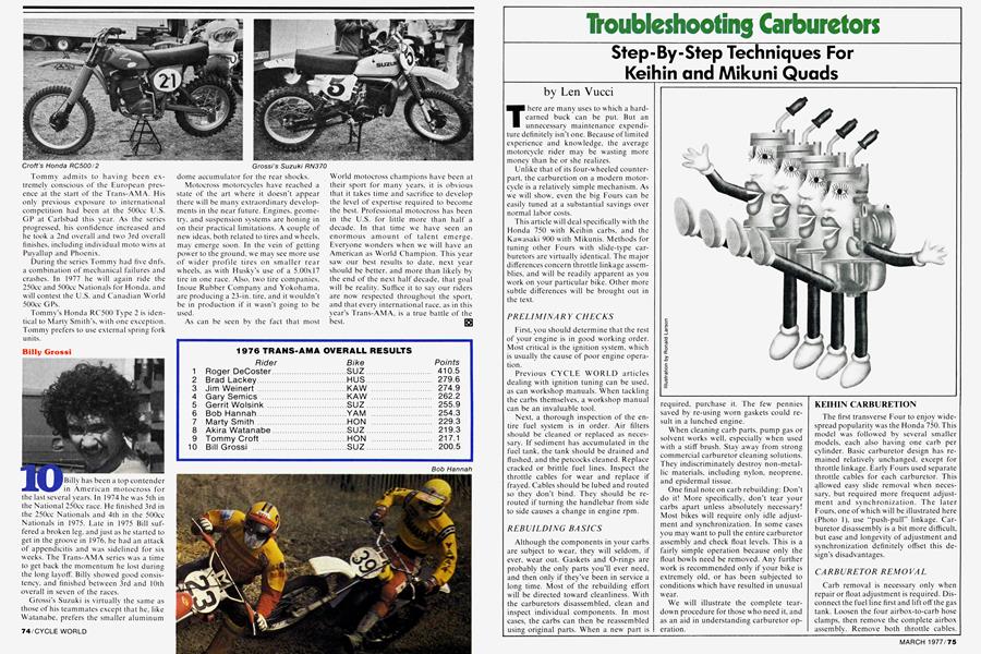
This article will deal specifically with the Honda 750 with Keihin carbs, and the Kawasaki 900 with Mikunis. Methods for tuning other Fours with slide-type carburetors are virtually identical. The major differences concern throttle linkage assemblies, and will be readily apparent as you work on your particular bike. Other more subtle differences will be brought out in the text.
PRELIMINARY CHECKS
First, you should determine that the rest of your engine is in good working order. Most critical is the ignition system, which is usually the cause of poor engine operation.
Previous CYCLE WORLD articles dealing with ignition tuning can be used, as can workshop manuals. When tackling the carbs themselves, a workshop manual can be an invaluable tool.
Next, a thorough inspection of the entire fuel system is in order. Air filters should be cleaned or replaced as necessary. If sediment has accumulated in the fuel tank, the tank should be drained and flushed, and the petcocks cleaned. Replace cracked or brittle fuel lines. Inspect the throttle cables for wear and replace if frayed. Cables should be lubed and routed so they don’t bind. They should be rerouted if turning the handlebar from side to side causes a change in engine rpm.
REBUILDING BASICS
Although the components in your carbs are subject to wear, they will seldom, if ever, wear out. Gaskets and O-rings are probably the only parts you’ll ever need, and then only if they’ve been in service a long time. Most of the rebuilding effort will be directed toward cleanliness. With the carburetors disassembled, clean and inspect individual components. In most cases, the carbs can then be reassembled using original parts. When a new part is required, purchase it. The few pennies saved by re-using worn gaskets could result in a lunched engine.
When cleaning carb parts, pump gas or solvent works well, especially when used with a stiff brush. Stay away from strong commercial carburetor cleaning solutions. They indiscriminately destroy non-metallic materials, including nylon, neoprene, and epidermal tissue.
One final note on carb rebuilding: Don’t do it! More specifically, don't tear your carbs apart unless absolutely necessary! Most bikes will require only idle adjustment and synchronization. In some cases you may want to pull the entire carburetor assembly and check float levels. This is a fairly simple operation because only the float bowls need be removed. Any further work is recommended only if your bike is extremely old, or has been subjected to conditions which have resulted in unusual wear.
We will illustrate the complete teardown procedure for those who need it, and as an aid in understanding carburetor operation.
KEIHIN CARBURETION
The first transverse Four to enjoy widespread popularity was the Honda 750. This model was followed by several smaller models, each also having one carb per cylinder. Basic carburetor design has remained relatively unchanged, except for throttle linkage. Early Fours used separate throttle cables for each carburetor. This allowed easy slide removal when necessary, but required more frequent adjustment and synchronization. The later Fours, one of which will be illustrated here (Photo 1), use “push-pull” linkage. Carburetor disassembly is a bit more difficult, but ease and longevity of adjustment and synchronization definitely offset this design’s disadvantages.
CARBURETOR REMOVAL
Carb removal is necessary only when repair or float adjustment is required. Disconnect the fuel line first and lift off the gas tank. Loosen the four airbox-to-carb hose clamps, then remove the complete airbox assembly. Remove both throttle cables.
Loosen the four clamps on the carb side of the connecting hoses. The carburetor assembly can then be eased to the rear and off the engine (Photo 2). Remove the four vent hoses from the carburetor float bowls.
FLOAT INSPECTION
Slide the retaining wire over, and remove the float bowl (Photo 3). Pull out the pivot pin, and lift ott' the floats. Remove the float valve needle, and inspect its tip (Photo 4). If it is grooved, replacement of both the needle and seat will probably be necessary.
FLOAT ADJUSTMENT
Replace the float assembly on the carburetor. Place the carbs on a flat surface, air cleaner side down. Measure the distance from the carb base to the float edge (Photo 5). Proper float height is 26 mm. If necessary, adjustment is performed by bending the tang on the float bracket. Repeat this procedure for each of the four carburetors.
Unless you wish to disassemble the carburetors, the float bowls should now be replaced, and you should proceed to the section entitled CARBURETOR REINSTALLATION.
CARBURETOR SEPARATION
To avoid damaging the floats, remove them or replace the float bowls. Disassembly is easiest if the carbs are removed in pairs. After disconnecting the throttle return spring, the choke linkage should be disconnected at either center carb (Photo 6). Slide the rubber boots up and off the adjusters. Remove the four flat-head Phillips screws that secure the carbs, and slide them out of the assembly (Photo 7). The throttle return spring anchor makes removal a bit hard, but not impossible. Each pair of carbs, held together by the fuel inlet T-fitting and a vent tube, can simply be pulled apart.
CARBURETOR DISASSEMBLY
Unscrew the carb top. and extract the throttle slide. Use a Phillips screwdriver to remove the two screw s that secure the slide to the shaft bracket (Photo 8). The needle can now' be removed and checked for wear. It should be smooth and straight.
JET LOCATION
If you have not already done so, remove the bowl and float assembly. Remove the pilot jet, main jet, and emulsion tube (Photo 9), and make sure their passages are clear. Replace the needle jet if necessary. The needle jet may be pushed out through the main jet hole, using a small wooden dowel.
IDLE SCREW CONFIGURATION
Earlier model 750s use a standard idle mixture screw (Photo 10). Later models use a pressed-on plastic cap (Photo 11) to limit idle mixture adjustment to approximately Vs turn. If you wish to remove the late model idle screw, first note the position of the plastic cap, then remove it.
Carefully turn the idle screw clockwise until it lightly seats, noting exactly the number of turns necessary. When the idle screw is removed and replaced, seat it lightly, then back it out the same amount, replacing the plastic cap. Should you forget to check the original position, back the idle screw out VA turns, then replace the cap.
CARBURETOR REASSEMBLY
After thoroughly cleaning the carburetor body and individual components, the carb can be reassembled. Replace the jets, float valve, float and pivot pin. Place the float bowl on the body, and snap the retaining wire into place.
Drop the jet needle into the slide, and fasten the throttle rod. Guide the throttle slide assembly into its bore, then tighten the carb top.
Repeat this procedure for the remaining carburetor of this pair. With serviceable 0rings on the fuel inlet T-fitting, this carb pair can be reunited.
Remove the remaining pair of carbs from the base flange, and perform the same operations on them.
All four carbs can now be refastened to the base flange. Make sure the throttle return spring anchor is in place between the center carbs. Place all choke valves in the off position, and replace the choke linkage rods. Check that each choke valve closes and opens fully, and adjust the linkage if necessary*
CARBURETOR REINSTALLATION
Looking into the bores of the carburetors, turn the throttle shaft to full open position. All four slides should fully retract into their bores. If not, adjustment of the throttle stop screw (Photo 12) is necessary. This step ensures full throttle operation.
Replace the throttle return spring. Reinstall the carburetor assembly on the engine, and tighten the connecting hose clamps. Reconnect the throttle cables, adjusting them for a very slight amount of slack. Check for full throttle opening and closing, and readjust the cables if necessary. Reinstall the airbox and carburetor vent tubes, but do not replace the gas tank.
Instead, use an additional length of fuel line to allow the tank to be remotely located. This makes carb adjustment much easier.
GETTING STARTED
Non-limited (earlier) idle mixture screws should be turned until seated, then backed out a full turn. Those with plastic limiter caps should be in their original positions.
Turn the fuel petcock on, and allow a half-minute for the float bowls to fill. If all connections and surfaces remain dry, start the engine, allowing it to reach operating temperature.
IDLE ADJUSTMENT
Adjust the idle speed screw (Photo 13) for 1000 rpm. Turn “non-limited” idle mixture screws in until a decrease in rpm is seen, then back out for smoothest running. Adjust “limited” idle mixture screws in the same manner, within the range of adjustment (% turn). Reset idle speed to 1000 rpm.
CARBURETOR SYNCHRONIZATION
To sync the carbs, we will use the Carb Stix described in last month’s article. Replace the vacuum tap screws in each of the carburetors with a Carb Stix nylon fitting (Photo 14). Connect the vacuum hoses, and start the engine. Mercury levels on the Carb Stix within a two centimeter (one division) distance (Photo 15). If not, loosen the locknuts (Photo 16) on the throttle rods, and turn the adjusters. Recheck sync after tightening the locknuts.
Remove the Carb Stix hoses and fittings, and replace the vacuum tap screws. Slide the rubber boots back over the adjusters. Reinstall the gas tank and fuel line.
MIKUNI CARBURETION
Except for Hondas, virtually all Multis use Mikuni carburetors. Again, throttle linkage configuration may differ, but basic operation and tuning methods will not. There is, however, one difference in idle circuitry which should be pointed out. Earlier Mikunis utilize an idle mixture screw located on the side and toward the rear of each carburetor. The Kawasaki 900 (Photo 17), has this type of carb, and will be used to illustrate tuning procedures.
Later models, such as the Kawasaki KZ1000 and KZ650 (Photo 18), have a slightly different idle system. The original screw location is blocked off. and the idle screw is now located under the carburetor, towxird the front of the float bowl. This screw' may have a plastic cap which limits rotation to about turn.
Early Suzuki GS750 carbs utilize sidemounted idle screws, w'hile later models will have the bottom-mounted versions.
Adjustment of the bottom-mounted idle screw is very critical, as it has a pronounced affect on low' speed running. If improperly adjusted, it can cause poor low' speed performance and increased fuel consumption. It may also significantly increase exhaust emissions. Eor these reasons, the manufacturers are very explicit in their adjustment procedures. In fact, the GS750 service manual states that the original setting is not to be disturbed. Period.
Adjustment procedures will be given for both versions of carbs. We do. how'ever, caution you not to attempt gross adjustment on the newer carb unless absolutely necessary.
CARBURETOR REMOVAL
Because the most difficult rebuilding task is the removal of the carburetor assembly, on-the-bike tuning should first be attempted.
The first step in getting the carbs off is gas tank and side cover removal. The eight hose clamps should be loosened. After sliding the carburetors to the rear (no easy task), disconnect the throttle cables and bottom vent hoses. The entire assembly can now' be worked free, and extricated from the left side.
FLOAT INSPECTION
Removal of four Phillips screws allows each float bowl to be lifted oft’, revealing the floats. Pull the pivot pin. and inspect the valve needle. A grooved needle should be replaced, as should its valve seat.
FLOAT ADJUSTMENT
Replace the needle, float, and pivot pin. Place the carb assembly on a flat surface, airbox side down. With the float resting against its needle, level should be 24 mm (Photo 19) for this carburetor type. Float
level will be di flerent for other models, but can be found in your owners’ or workshop manual. Adjust the float level for each carb.
Unless you w'ish to completely disassemble the carbs, replace the bowls, and proceed to CARBURETOR REINSTALLATION.
CARBURETOR DISASSEMBLY
Remove the throttle return spring. Three Phillips screws secure each of the carb tops. Remove all four tops. Remove the hex nuts (Photo 20) securing the throttle arms, and the hex nut holding the throttle cable pulley. Remove the single Phillips screw holding the throttle set plate (Photo 21). The two rubber shaft plugs should also be removed.
The throttle shaft will now slide out of the assembly.
The individual throttle slides may be drawn out of their bores (Photo 22). Mark each of the slides so it may be replaced in its proper bore. If the slides are switched, synchronization will be substantially more difficult.
The needles should be checked for wear and straightness. Each may be removed by unscrewing the two Phillips screws at the bottom of the slide.
JET LOCATION
The pilot jet, main jet and emulsion tube are accessible with the float bowl removed (Photo 23). With the emulsion
tube removed, the needle jet may be pushed out, using a piece of wooden dowel.
CARBURETOR SEPARATION
Unless one wishes to inspect the starting circuit assembly, there is usually no reason to separate the carburetors. Should you desire, however, removing the flat-head Phillips screws at the carb base allows separation.
IDLE CIRCUIT CONFIGURATION
The early variety carbs on this KZ900 utilize side-mounted idle mixture screws (Photo 24). On later carbs, a solid plug is screwed into that location. The pilot screw is then relocated to the float bowl front.
Both types seal the screw with an 0-ring, .which should be in usable condition. Again, we caution you to return the newtype pilot screw to its original position if removal is necessary.
CARBURETOR REASSEMBLY
With all components clean and serviceable, reassembly is a fairly simple task.
All jets should be in place, and floats properly adjusted. The float bowls should then be reinstalled. Place each slide assembly into its proper bore. Slide the throttle shaft into place, with the throttle pulley between the center carbs. Install and tighten the five shaft bolts. Replace the set plate and two rubber shaft caps. The four carburetor tops will be installed after synchronization.
Turn the throttle shaft to full open, and adjust the throttle stop screw (Photo 25) so the slides open fully. The throttle return spring should be hooked back on to complete this procedure.
CARBURETOR REINSTALLATION
Work the carb assembly back into place, and refasten the throttle cables. The carbs may have to be pushed down slightly to facilitate cable hook-up and adjustment. Check for full opening and closing of the throttle, and readjust the cables if necessary.
Tighten the eight hose clamps, and reconnect the float bowl vent hoses.
Place the fuel tank nearby, but oft' the bike. Use additional fuel line for the connection.
GETTING STARTED
On K.Z900 carburetors, turn the idle mixture screw in until lightly seated, then back out IV2 turns. The idle screws on late versions should be in their original positions.
Turn on the fuel petcock, allowing the float bowls to fill. Check for fuel leakage. If there is none, start the engine and let it warm to operating tempurature.
IDLE ADJUSTMENT
Adjust idle speed to 1000 rpm. On early version carbs, turn each idle screw in until a drop in rpm occurs, then back out until the engine runs smoothly. On late version carbs, staying within the limits of the stops is recommended. If there are no adjustment limiters, a Vs turn or so in either direction should suffice in most cases. Reset idle speed if necessary.
CARBURETOR SYNCHRONIZATION
At the base of each intake tube is a fitting for a vacuum attachment. Remove the rubber caps, and attach the Carb Stix hoses (Photo 26). With the engine running, mercury levels in the Carb Stix should be with a two centimeter (one division) distance. If not. loosen the locknut (Photo 27) on the carb(s) as necessary, and turn the adjuster for proper sync. Recheck synchronization after tightening the locknuts, then reset idle to 1000 rpm.
Remove the Carb Stix hoses, and replace the rubber caps. Install the four carb tops, and mount the fuel tank in its proper location.
PROCEDURAL SUMMARY
1. Inspect the fuel tank, air filter, throttle cables, and related components. Clean or replace as necessary. 2. Remove carburetor assembly. 3. Perform maintenance and cleaning. 4. Reinstall carburetor assembly and reconnect cables. 5. Adjust idle. 6. Synchronize carburetors. 7. Replace fuel tank.
Going back a bit, this series has dealt with carb theory, Singles, Twins and Triples, and now Fours. The heavy stuff is past, but there are still a few loose ends to tie.
Constant velocity carburetion is next, to be followed (for you Harley people) by fixed venturi (side-draft) carburetion. The Lectron carburetor, and any other new product which arises in the interim, will be the last in this series. So stay tuned!