Hondamatic: How It Works
Hondamatic: How it works
Fernando Belair
HONDA'S AUTOMATIC is not, in the true sense of the word, an automatic. Rather, it is a semi-automatic, very similar in performance to that of the first Volkswagen Automatic. The rider selects either a low or a high ratio and the torque converter takes care of the power delivery in the manner that provides the best possible acceleration. Still, the Hondamatic is a very intriguing animal. We thus decided to take a look inside one to see exactly how it works.
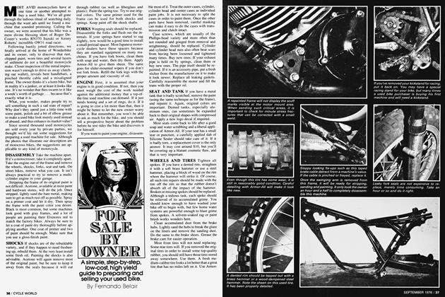
The Automatic's shift-mechanism is merely a three-position hydraulic valve. The left splined shaft is for the automatic neutral locater that is operated by an arm attached to the descending sidestand. The central splined shaft is the actual shift shaft. The splined shaft at the lower right is for the emergency kickstart pedal that is stored beneath the seat.
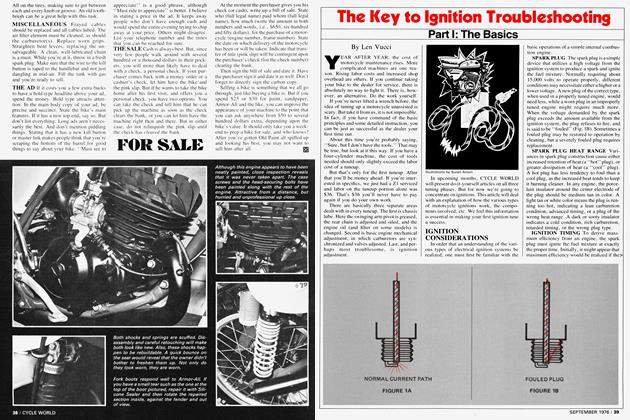
Beneath the shift mechanism are two trochoidal pumps. Both of them draw through the filtered scavenger from the wet sump. One pump is used to feed the engine and lubricate the mainshaft and output shaft bearings. The other pump is slightly wider and is purely a pressure pump whose job it is to fill the torque converter and the particular pressure-activated clutch selected through the shift mechanism. Engine pressure is normally about 70 psi, while the pressure in the torque converter and clutches can be as high as 180 psi.
With the shifter mechanism and oil pumps out of the way, the oil passages can be seen near the protruding kickstart shaft. Oil is drawn through one of these tube-like passages and then pressure-fed back through the others to the maze-like galleys at the bottom of the engine. The galley-filled plate opposing the galleys cast into the crankcase directs the oil to either the engine or the torque converter and clutches, depending upon the galley. Before reaching the torque converter, the high-pressure oil passes a relief valve. The valve also contains a relief override, the spring for which is partially visible in the photo.
The high-pressure oil travels through cast-in passageways until it arrives at the exposed outer plate. As can be seen, five of the seven holes are cut all the way through and are used for bolts that secure the plate. The other holes are oil passageways. The top one receives the oil and directs it to the center of the hollow shaft from which the torque converter gets filled. The left hole is a return hole that is blocked by a lightly sprung dowel in order to prevent the torque converter from draining when the engine is in neutral and no transmission pressure is being created. When low gear is selected, the oil pressure forces circulation in the torque converter for the purpose of cooling. As fresher oil is fed in, the existing oil drains past minute semi-circular cutouts on the inner surface of the bushing that rides over the visible splined shaft. This pressurized oil causes the dowel to recede and allow the oil to pass back into the sump.
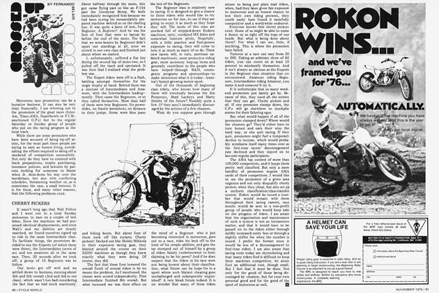
Honda’s torque converter consists of three basic parts and is very much like torque converters on automatic automobile transmissions. The three parts are the pump (left) the stator (center) and the turbine (right). As you can see by the varying sizes of the individual center holes, each rides on a different concentric shaft. The pump is the only part of the engine that is directly driven by the engine. As the engine is revved, the pump’s vanes throw oil at the turbine’s vanes, rotating the turbine and the center shaft of the concentric shafts. It is on this shaft that the low-gear clutch rides. The turbine's vanes receive the high-speed oil and send it, through its central vanes, back at the pump. Unfortunately, at this point the returning oil is exerting force in the opposite direction of the pump’s revolutions. This is where the stator comes in.
The stator is the smaller vaned device that rides on the mid-sized concentric shaft. It is equipped with a one-way clutch that allows it to spin only in the same direction as the pump and turbine. As long as the differences in speed between the engine-driven pump and the gear-driving turbine are great enough to keep the stator pressed back against the clutch’s lock, the turbine just sits there, its vanes altering the direction of the turbine’s returning oil so that it can be picked up once again by the pump and reused.
Since oil that has passed through the stator is now traveling in a direction favoring the pump, the oil’s forces act to increase the torque force exerted by the pump on the turbine. Therefore the stator acts as a torque multiplier.
In addition, the stator’s shaft is fitted with an arm that rides directly above the transmission relief override. When the oil pressure against the stator is great enough, such as under hard acceleration, the arm activates the relief valve override and pressure in the torque converter increases, improving oil flow for better cooling. As the speed of the gear-driving turbine begins to match that of the engine-driven pump, a simple fluid coupling takes place with the stator now spinning merrily along.
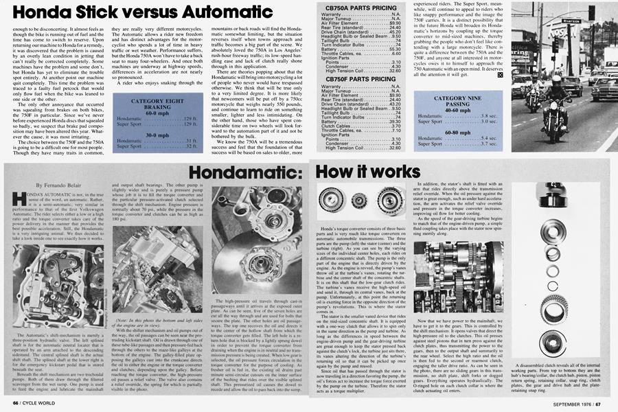
Now that we have power to the mainshaft, we have to get it to the gears. This is controlled by the shift mechanism. It opens valves that direct the high-pressure oil to the clutches. This oil presses against steel pistons that in turn press against the clutch plates, thus transmitting the power to the gears, then to the output shaft and summarily to the rear wheel. Select the high ratio and the oil is then fed to the second or rearmost clutch, engaging the taller drive ratio. As can be seen in the photo, there are no sliding gears in this transmission, no shift plate, shift forks or dogged gears. Everything operates hydraulically. The O-ringed hole on each clutch collar is where the clutch actuating oil enters.