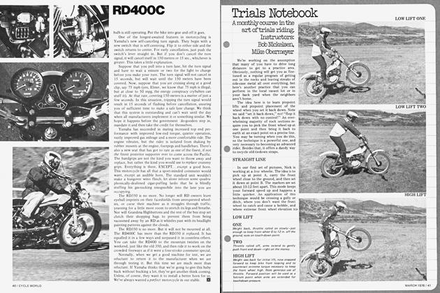
Making Kawasaki's Superbike Super Prrt Ii
MAKING KAWASAKI'S SUPERBIKE SUPER PRRT II
TECHNICAL
HOW TO INSTALL THE ULTIMATE HOP-UP KIT IN THE Z1
WALT FULTON
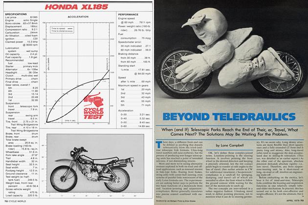
AFTER READING last month’s low-budget fix and carrying out the suggested modifications, your bike, like ours, is one of the best on the road. A minimum of expense (the tires accounted for most of the cash outlay)and several hours of work were all it took. But now things are getting a bit more complicated and more care and tools are required. You may have noticed that last month we omitted the charts showing the proper sequence for tightening the cam tower bolts and head bolts. Those charts are included here and are again necessary.
In the March 1974 issue of CYCLE WORLD we road-tested the DuHamel Replica Zl. For an exchange price of $1767.49 you could have had the same bike that we ran through the quarter in 11.40 sec. at 116.88 mph. The bike comes in two sizes, 987cc or 1002cc; ours was the smaller. Since the introduction of that Stage 1 engine, Dale-Starr has perfected what is claimed to be the ultimate combination for the street rider, a combination that has more muscle and performance, and that is easy to ride to boot.
The Stage 1 engine mods amounted to nothing more than cams, valve springs and larger pistons of your choice. Stage 2 engine constitutes a world of difference. It includes the aforementioned parts, as well as a racing head, which consists of porting, polishing, combustion chamber modifications, valve springs and guides.
Our engine modifications go one step farther, since we have chosen some special combinations from the DaleStarr catalog. To begin with, the actual bore is 994cc, with slipper and two-ring pistons. An aluminum layered head gasket, larger valves, a ported head, Road and Track camshaft, and a chrome Dale-Starr four-into-one exhaust system complete the package.
In building any engine for the street there are a couple of very important design considerations to be kept in mind. Don’t forget that while we tried to put a $100 ceiling on expenditures for last month’s project, cost is not a consideration now. Using components that complement one another is. Experience tells us that putting together a hodgepodge of single pieces, one from here, one from there, will most often net the potential builder nothing more than a big headache. Certainly, by using a potpourri of unmatched parts, the maximum performance potential of an engine won’t be reached. But even if it’s not slower, is it streetable? That is the most important question when building a “hot” street bike.
FRAME MODS
When building the ultimate Z1 engine, the gigantic horsepower increase necessitates certain frame mods that offer precise steering and better handling not only through corners, but even in a straight line. That’s right, in addition to being a requirement for the 994’s horsepower, the kit will instantly make a better handler out of any stock Z.
Engine removal is quite straightforward. Motor mounts, chain, electrical connections, throttle linkage, carbs, etc., go first. While all of this is going on, the filter and drain plug should be out and the oil draining. This goes faster if the engine is warm. Taking the engine from the frame damn near requires three hefty people, one to steady the bike and two to lift. If you have some means of tying the bike down, two people should suffice.
In order to position the kit pieces at the flex points, the test frame was nickel-plated, a high horsepower engine installed and the bike run at a test track. The fatigue points showed up when the nickel began to flake off and reveal signs of stress. Braces were added, the frame replated and the bike returned to the race track. Lo and behold, yet another stress point revealed itself. After plating, welding and traveling to the track several times, the frame finally attained enough rigidity for the best racer on the circuit. Along with bracing the frame, the swinging arm was heavily gusseted to keep the rear wheel traveling in a straight line at all times.
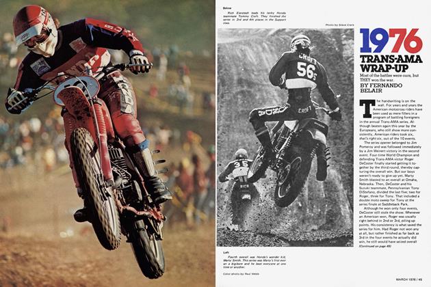
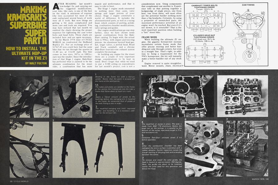
Although there probably aren’t too many of you out there who have access to a heli-arc welder, one is necessary to keep the concentration of heat to a minimum in order to prevent changing the structure of the frame material. But any welding shop can attach the kit for you at a small fee. It is most important that some frame preparation be done, however. To do so, use a file or coarse sand paper to remove all paint from the areas where the tubes and plates will be added. Photo 1 A shows the kit installed.
On 1975 and earlier Zs the only trouble you are likely to run into is properly positioning the rear frame plate. Just make sure that there is clearance for the airbox when it is installed in the frame. On the 1976 (and presumably later) 900s, the airbox presents more of a problem, but not one that can’t be overcome.
The baffling chamber at the end of the airbox must be discarded. Whatever you do, you shouldn’t remove the entire air cleaner system, as this detunes the engine. The plastic shroud should be cut to clear the rear plate. The standard air cleaner isn’t used. This creates a dead air space and prevents a fluctuation in carburetion caused by air turbulence across the intakes. The remaining air induction system provides two needs: a venturi at the carb intakes and a fine, wire mesh screen that will at least keep big chunks of junk out of the carbs.
Unbolt the shocks from the swinging arm, undo the pivot bolt and slide the shaft through the arm and out of the frame. When installing the gusseted arm, don’t forget to thoroughly grease the bushings. Since all swinging arms and frames are not the same width, you may have to pry the frame apart to fit the arm. Once in place, tighten with a slight amount of preload.
After the frame has been welded, take a can of black spray paint and touch up the attachment points. If the paint is applied with some semblance of artistry, the frame will look brand-new.
At this point in the game it would be a good idea to fit the oil cooler to the brackets already provided on the frame. The Lockhart cooler does attach to these brackets and requires no more work than simple mounting according to the instructions. The kit comes with all the necessary hardware, cable ties to fasten the oil line to the frame, oil pickup and return fittings for the engine, nuts and bolts, hose clamps and an ample length of nylon-reinforced hose. (Correct length of the hose can be determined when the engine is in the frame).
So much for modifications to the Zl’s frame. They sound simple, but make all the difference in the world. Now we’re ready to delve into the deep, dark recesses of the engine, perform a little magic and produce a rocketship street bike. Again we’d like to emphasize that all the pieces used on the Z1 are standard cataloged parts, sold in kit form or separately.
ENGINE MODS
There will be some of you who don’t have the tools, the desire or the knowledge to tear into your engine and perform these modifications and install the correct parts. Those who fall into that category can have their dealer do the work or send their engine to DaleStarr. Before rolling up your sleeves and digging in, remember that it is of paramount importance to have the proper tools: rotary files and a power source, a complete set of wrenches, sockets and an impact driver, degree wheel and a dial indicator, a mechanical stop for finding TDC, a base to hold the pistons steady when fitting the cylinder, some means for rotating the cams and a scribe to indicate proper timing marks.
Okay, let’s get started. We had the advantage of using an engine stand; you probably won’t. So, turn the engine upside down and rest it on the bench, supporting it by wooden blocks until secure. Remove the 6mm bolts that hold the oil pan to the cases and lift off the pan.
Under normal circumstances, the oil pump on the 903 does a satisfactory job, but during periods of hard acceleration all the oil is forced to the rear of the engine; the pump pickup, at the front, can get nothing but air. This is called cavitating. Naturally, no oil gets to the top end to lubricate the moving parts. This can be expensive if it happens too often. When gassing it away from a stop, any Z1 owner can attest to the oil warning light coming on and not going out for several seconds.
Kawasaki has been aware of the cavitating problem from the beginning. To solve it they have installed an oil pan that allows for greater capacity, and added baffles to slow the flow of oil to the rear. But this only skirts the problem. Now when the bike is gassed, the oil still flows to the rear of the engine and the pump cavitates, but it does so even longer because the baffles prevent the oil from returning to the pickup as quickly.
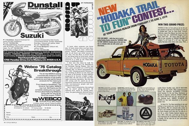
There is no way to keep oil at the pump at all times, but there is a partial remedy. By closing off the pickup, drilling a hole in the side of the pump, and welding in a 6 or 7-in. length of 1 /2-in. ID pipe (see photo 4), the oil can be picked up at the rear of the engine when accelerating, as well as at normal cruise. The only time that oil won’t be picked up is under braking, at which time it is forced to the front of the engine. But at least then the throttle is closed, lubrication requirements are lessened and heat is lower. It is a trade-off to be sure, but this is by far the better situation.
In addition to the welding, the pickup tube requires a bend or two in it. For best results we recommend sending the pump to Dale-Starr for modification. You can remove the baffles in the sump —to accommodate the pickup tube—yourself if you have a rotary file. To prevent scarring, place a shop towel around the pan and secure it in a vise before removing the two baffles cast between the oil filter register and the outside of the case. Round off all the edges and smooth them until even with the rest of the case.
Once the baffles have been removed and the pump modified, replace the gasket with a new one and button up the bottom of the engine. Turn the engine over and support it once again with wooden blocks until completely steady before starting work on the top end.
Begin by removing all of the 6mm bolts that hold the cam cover to the head. If you picked up on last month’s story you’ll remember that these bolts are made of relatively poor material and shouldn’t be mixed up with any others in the top end. The chain idler gear and cams can be removed and set aside. It may be necessary to use a plastic or rubber mallet to break the seal between crankcase/gasket/cylinder. Once it is free, position the pistons equally in the cylinder and raise it slightly so that shop towels can be forced around the bottom of the pistons. This will, hopefully, prevent any foreign objects, such as pieces of piston ring, etc., from falling into the case. Now, carefully pull the cylinder off of the pistons and studs.
Use a sharp, pointed object, such as a sharpened spoke or a scratch awl, to dislodge one piston pin circlip from each piston. Provided the engine hasn’t been too hot, the pins should slide right out. If they don’t, a universal pin puller must be used.
All of the necessary head work is done on an exchange basis by DaleStarr. You send your head in and get back another that has been ported and polished for whatever combination you have chosen. It is impossible for the average backyard tuner to perform all of the operations that go into properly setting up the head, so we won’t give precise porting specifications, but will tell you generally what goes on and why. The people who port these heads for a living spend approximately 11-1/2 hours on each one, so you can see that it is no easy task. Add another two to four hours for the valves.
The basic port diameters remain unchanged; they are slightly contoured and highly polished to produce a smooth flow and maximum acceleration and speed of the incoming and outgoing gases through them. Each Special Racing Head leaves Dale-Starr with a mirrorlike finish in the ports.
The biggest improvement to the head is a trough that is cut in the combustion chamber between the valves. This passage helps to propagate the flame front when the plug is fired, aiding in a more complete combustion of the compressed gases. The combustion chambers are finished to a mirror surface.
New valve guides, made from a tougher material than the standard ones, are installed. They are contoured and shaped to enhance the flow of gases. To remove or install them the head must be evenly heated until a drop of water will splatter on it (approximately 350 degrees). A pilot is used to install the guides. It then takes the head another 45 minutes or so to cool enough to go on.
Next, the valve seats are ground. Both the intake and exhaust are ground at multiple angles of 30, 46 and 60 degrees. To do this it is important to have the proper pilot, grinding stones and drill motor. Both inlet and exhaust valves are 1 mm larger in diameter than the standard ones. This is important to a certain extent, but the advantage is in the material of which they are made. It is an alloy that will withstand the high heat accompanying high horsepower output, as well as sustained high rpm.
As you can see, the head requires a great deal of work, which only those with all the right tools and knowledge should attempt. For $450 most people are far ahead to purchase the Racing Head complete.
Once the 994cc pistons are obtained, the cylinder is bored to the prescribed oversize, in this case an increase of 3.25mm per cylinder. The alloy materials used in a piston are of prime importance. . .particularly so with this setup. Piston-to-cylinder clearance is a mere .001 5 in. This does necessitate a fair bit of break-in before the throttle is opened up, but produces a better seal, quieter running and more life from a set of pistons.
The diameter of the piston is measured 5mm from the bottom of the skirt, 90 degrees from the pin. Notice that the pistons have only two rings. This reduces friction, yet still allows for a good seal during combustion. This type of piston has been used, and still is, in the 24-hour racing bikes in Europe, which certainly attests to its reliability.
In looking at the photos many will think that the piston crowns aren’t high enough, but the old-school belief that high compression means high hp doesn’t apply here. The idea is to draw a maximum charge into the cylinder on the intake stroke. Not only does a high dome preclude this, but it also interrupts the flow of gases at valve overlap. The piston tops are matched to the design of the combustion chamber to allow for the maximum available flow of fresh charge into the chamber. Our engine was set up with a clearance of .065 and .080 between the piston and the inlet and exhaust valves, respectively.
Install the pistons on the rods and secure the circlips. The pistons must be positioned evenly and held steady by a rod running between the piston bottoms and the crankcase. Apply a liberal amount of oil to the pistons and cylinder bores, place the cylinder over the studs and onto the pistons. The taper at the bottom of the cylinder is all that is needed to compress the rings. Carefully work the cylinder over the rings and onto the pistons; a small flat-blade screwdriver will help.
Before going any farther, attach a mechanical stop to the studs of the number one cylinder. Remove the alternator cover and attach a degree wheel to the end of the crankshaft. Attach a pointer (small-diameter rod) to the engine casting on that side and bend it over the edge of the wheel. Carefully run the piston up to the stop in one direction and note the degrees on the wheel; repeat in the opposite direction, split the difference between the two and that is TDC. Remove the stop, turn the crank until TDC is reached and set the degree wheel to 0 degrees TDC.
Before reassembling the head there are several setup tasks that must be performed. The first has to do with the drive gears on the cams. Firmly tighten one gear in a vise and, using a rattail file, elongate each of the three 6mm holes approximately 1/8 in. in each direction. Repeat with the other gear. The position of the gear can now be changed when it comes time to degreein the cams.
Put the gears back on each camshaft, place one cam or the other in the head and tighten down with the cam towers. Do not put both cams in at the same time; if this is done, there is a possibility of bending a valve or two while setting the tappet clearance. With this particular head, two of the valve seats were not cut deep enough to accommodate the length of the valve stem. The valves thus had to be removed and the stems shortened on a valve grinding machine. Once this was done, tappet clearance was adjusted to between .006 and .008 in. In this case a spanner (made from excess cam chain brazed to a handle) was used to rotate the cams (photo 15).
To assure a proper spring pack, total travel of the spring is measured. Once peak opening of the valve is obtained, the springs should coil bind in another .050 to .070 in. If this has to be adjusted, shims (included) must be fitted under the spring (photo 17).
A two-piece, layered aluminum head gasket was used in our engine. In the past there was some problem with oil seeping out between the head and cylinder where the cam chain runs. The two-piece gasket is to prevent this; oil at the center is retained by the standard sealing ring. The gaskets are located by way of notches cut in them and bent around the inside studs (photo 19).
Before the gaskets are put in place, they are sprayed with a copper coating, heated, cured and sprayed again. This aids in sealing the combustion mixture.
When the head is put into place with both cams removed, make certain that the cam chain is free (photo 20). Go ahead and torque the head to the specified figures.
The camshafts can now be placed in the head and timed according to the instructions in the first installment. Don’t forget to tighten down the cam towers in the prescribed sequence (see diagram). Fit the cam chain idler gear.
You’re now ready to degree the cams in. This is where the cam gears with the elongated holes come into play. But first, the cam chain must be tightened to its limit.
By doing this, the opening and closing of the valves can be controlled more precisely. With the adjuster rod loose, back the whole housing away from the cylinder 1/8 to 1/4 in. Tighten the adjuster down and retighten the housing to the cylinder. (Continued on page 82)
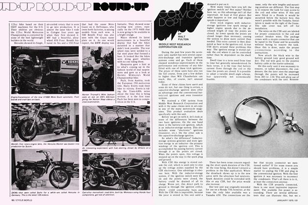
PARTS LIST
*These are prices of the optional parts installed in the Stage II engine. They sell separately for $169.95 and $447.31, respectively. **There is a labor charge of $108 to remove the engine, weld the frame, replace the swinging arm and reinstall the engine.
Continued from page 65
With the number one cylinder at TDC (which has already been established on the degree wheel), place a dial indicator on the inlet spring cup. Rotate the engine in a clockwise direction until the gauge reads 1mm (.040 in.) of travel. Twenty-five degrees BTDC should line up on the wheel and pointer; if it doesn’t, loosen the bolts on the drive gear and rotate the crank until it does. Make sure the cam doesn’t move! Torque down the drive-gear bolts. Repeat the process for the exhaust cam. Use the 1mm reading on the dial gauge and 20 degrees ATDC for timing.
Believe it or not, that’s all there is to degreeing a cam. It’s really a heck of a lot easier than most people think. All it takes is a little practice and patience. Mission accomplished; go ahead and close up the top of the engine.
The degree wheel is also used to accurately indicate where the timing marks should be placed on the advance unit. Just for fun, check and see where the standard marks are and how close they are to the correct setting. Chances are they’re off. Though they’re close enough for production work, we’re interested in getting the most out of what we have. The standard timing is 38 degrees BTDC. We scribed three new timing marks on the advance: 30 degrees, 35 degrees and 40 degrees BTDC.
After the points backing plate is removed, use a felt-tip marker to blot out the factory timing marks on the advance. Set the crank at the prescribed setting, picture an imaginary straight line between the stationary timing point in the case and the advance, and mark; rotate the crank to the next setting and repeat. Replace the backing plate and set point gap. Once the engine is back in the frame, timing can be set as per last month’s instructions.
Remove the degree wheel and replace the left cover. We used one that had the bottom corner cut out and a flat piece welded to it, which increases ground clearance. If you choose to do the same, care must be exercised when removing and replacing the alternator windings in the cover. Because of the porosity of the aluminum case, it is difficult to weld. Before reassembling check for any leaks.
The engine can now be lifted into the frame and bolted into place. Before the carbs are fitted they too must be tuned to a ballpark setting. Remove the top of the four carbs and take out the needles. Reposition them in the fourth notch from the top. Once that is done, pull the float bowl off and fit 117.5 main jets.
(Continued on page 84)
Continued from page 82
A chrome four-into-one exhaust pipe rounds out the package. No special mounts have to be devised, but the centerstand must be removed. . .a small inconvenience, but important for increased ground clearance. Much more inconvenient is the fact that, in order to change the oil filter, the pipes must be removed. That’s the price one must pay for performance.
A word about the pipe: all four headers are the same length, which is a requirement for equal tuning of the individual cylinders. The headers form a collector, and to that is mounted a muffler with an interesting history. It is a scaled-down version of the mufflers used on Plymouth stock-car racers. The baffle permits quiet operation at low rpm and slight throttle openings. At higher speeds and throttle settings the quieting part of the baffle is bypassed to allow for maximum horsepower output.
A Super Power Pac kit consisting of a Nyloplas sprocket, wide countershaft sprocket and number 60 chain is used to transmit the extra power to the rear wheel. This kit has eliminated the problems associated with high hp output.
After such a long-winded discourse on putting this beast together, there is no doubt one question in your mind: Is it worth it? Simply, the answer is yes, but because of lack of time and space, performance data are not included at this time. In subsequent issues I will compare the three levels of engine and frame performance, taking into consideration such things as quarter-mile times and speeds, fuel economy, handling, streetability, etc. Tune in next month for an inside look at the “street-legal” AMA production racer. [ÖJ
Don’t forget, the Z1 described here will be given away at Daytona, courtesy of Kawasaki Motors Corp., Dale-Starr Eng. and CYCLE WORLD magazine. If you haven’t already done so, simply put your name, age, address and telephone number on a 3 x 5 post card and rush it to CYCLE WORLD, Box 1757, Newport Beach, CA 92663, by March 1, 1976. You are not required to buy anything, including this issue of CW. You must be 18 years of age or older. Only one entry per person. No employees of CBS or affiliated corporations are eligible. This contest is void where prohibited by law.