How They Work And Why
How They Work And Why
Troubleshooting Carburetors:
Len Vucci
MOTORCYCLE CARBURETORS are interesting devices that pose some intriguing problems. The average owner begins by regarding the carb as sort of magic, an intricate mechanism understood only by the wizards at the dealership. The next step is to consider the carb a cure-all, secret switch that, if fondled correctly, can take care of any tuning problem.
Neither attitude is entirely accurate. Motorcycle carburetors are precision devices, doing complicated work with a minimum of actual trouble. Perhaps because they’re so easy to fiddle with, they get fiddled with. Most mechanics will tell you that 90 percent of normal tuning problems come from the ignition . . . and 90 percent of backyard mechanics tackle the carb first. (What the professionals may not say is that most of their work involves fixing what the owner did wrong, rather than what the carb did to itself).
Don’t become discouraged. Carburetors aren’t simple, but neither are they magic. Carbs can be maintained, repaired, modified or replaced by the owner. Doing the work properly requires first that the owner have a basic understanding of what the carb is, what it does and how it does it.
This is the first section of a two-part article. In the following pages we’ll take a fairly long look at the theory of carburetion, and at how the major carburetor companies apply that theory to production engines. As perhaps a side benefit, we’ll describe a popular aftermarket carb.
CARBURETOR DESCRIPTION
In the simplest possible terms, a carburetor meters, mixes and delivers air and fuel to the engine.
To do this, a carb has several components or systems.
OPERATIONAL DESCRIPTION
In order to give a preview of things to come, a brief general description of the separate carb functions follows.
THROTTLE: A means of controlling engine power and speed is necessary. The throttle controls the amount of air and fuel mixture admitted to the engine.
MIXTURE CONTROL: To satisfy various engine requirements, the air and fuel must be mixed in the proper proportions. The carburetor must produce the air/fuel mixtures necessary for cold starting and running, low-, medium-, and highspeed operation.
FUEL SUPPLY: To maintain consistent operation, the carburetor must have a steady fuel supply. The float mechanism ensures that fuel level is constant.
VENTURI EFFECT: Without exception, all carburetors utilize some form of venturi. Its effect is one of suction, to draw fuel to the area of the carb where it is needed.
With few exceptions, all carburetors must satisfy the above-listed requirements if reliable engine operation is to be achieved. Starting with float mechanisms, operational theory of the separate systems will now be given.
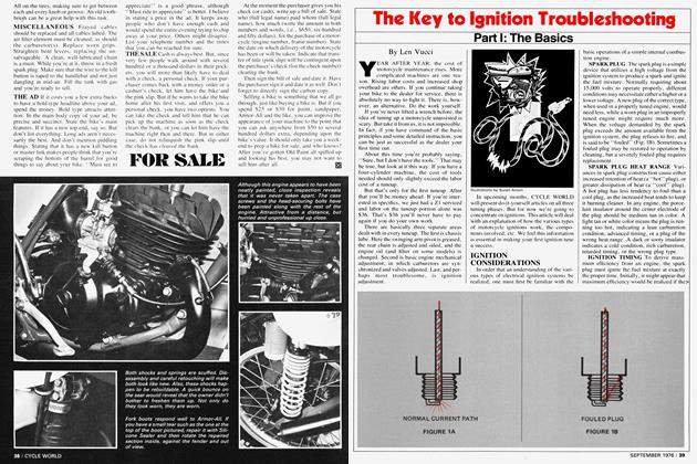
FLOAT MECHANISMS
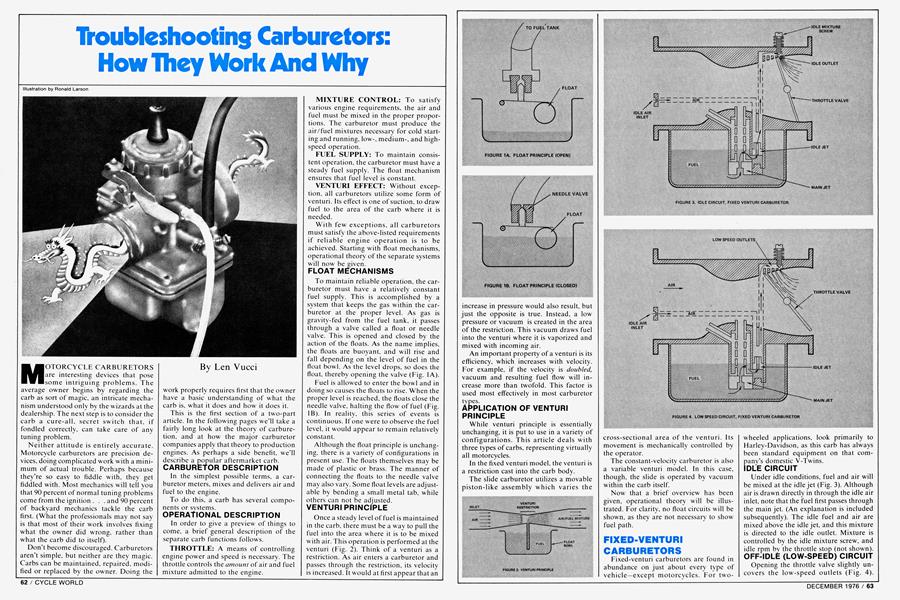
To maintain reliable operation, the carburetor must have a relatively constant fuel supply. This is accomplished by a system that keeps the gas within the carburetor at the proper level. As gas is gravity-fed from the fuel tank, it passes through a valve called a float or needle valve. This is opened and closed by the action of the floats. As the name implies, the floats are buoyant, and will rise and fall depending on the level of fuel in the float bowl. As the level drops, so does the float, thereby opening the valve (Fig. 1A).
Fuel is allowed to enter the bowl and in doing so causes the floats to rise. When the proper level is reached, the floats close the needle valve, halting the flow of fuel (Fig. IB). In reality, this series of events is continuous. If one were to observe the fuel level, it would appear to remain relatively constant.
Although the float principle is unchanging, there is a variety of configurations in present use. The floats themselves may be made of plastic or brass. The manner of connecting the floats to the needle valve may also vary. Some float levels are adjustable by bending a small metal tab, while others can not be adjusted.
VENTURI PRINCIPLE
Once a steady level of fuel is maintained in the carb. there must be a way to pull the fuel into the area where it is to be mixed with air. This operation is performed at the venturi (Fig. 2). Think of a venturi as a restriction. As air enters a carburetor and passes through the restriction, its velocity is increased. It would at first appear that an increase in pressure would also result, but just the opposite is true. Instead, a low pressure or vacuum is created in the area of the restriction. This vacuum draws fuel into the venturi where it is vaporized and mixed with incoming air.
An important property of a venturi is its efficiency, which increases with velocity. For example, if the velocity is doubled, vacuum and resulting fuel flow will increase more than twofold. This factor is used most effectively in most carburetor types.
APPLICATION OF VENTURI PRINCIPLE
While venturi principle is essentially unchanging, it is put to use in a variety of configurations. This article deals with three types of carbs, representing virtually all motorcycles.
In the fixed venturi model, the venturi is a restriction cast into the carb body.
The slide carburetor utilizes a movable piston-like assembly which varies the cross-sectional area of the venturi. Its movement is mechanically controlled by the operator.
The constant-velocity carburetor is also a variable venturi model. In this case, though, the slide is operated by vacuum within the carb itself.
Now that a brief overview has been given, operational theory will be illustrated. For clarity, no float circuits will be shown, as they are not necessary to show fuel path.
FIXED-VENTURI CARBURETORS
Fixed-venturi carburetors are found in abundance on just about every type of vehicle—except motorcycles. For twowheeled applications, look primarily to Harley-Davidson, as this carb has always been standard equipment on that company’s domestic V-Twins.
IDLE CIRCUIT
Under idle conditions, fuel and air will be mixed at the idle jet (Fig. 3). Although air is drawn directly in through the idle air inlet, note that the fuel first passes through the main jet. (An explanation is included subsequently). The idle fuel and air are mixed above the idle jet, and this mixture is directed to the idle outlet. Mixture is controlled by the idle mixture screw, and idle rpm by the throttle stop (not shown).
OFF-IDLE (LOW-SPEED) CIRCUIT
Opening the throttle valve slightly uncovers the low-speed outlets (Fig. 4). Mixed with the air flowing around the throttle valve, additional fuel is metered to maintain correct air/fuel ratio.
If further mixture adjustment is necessary, idle jet size may be changed.
MAIN CIRCUIT
For throttle openings greater than oneeighth to one-quarter, the main circuit comes into operation (Fig. 5). Fuel is drawn up through the main jet and mixed with air from the main jet air intake. This atomized mixture is then drawn into the venturi and passed on to the engine. As there is no mechanical metering of the main jet circuit, total fuel flow is determined by main jet size.
Although the main circuit is the primary source of fuel under normal conditions, the low-speed circuit still contributes a portion of this mixture. By routing the idle fuel path through the main jet. a leaner high-speed mixture is possible without losing mid-range and bottom end. Should one desire to alter high-speed fuel/air mixture, the main jet may be changed.
COLD STARTING
This type of carb, as well as some others, utilizes a choke to facilitate cold starting (Fig. 6). The choke (or butterfly) valve is turned so that it blocks almost the entire carb inlet. This causes an increase of vacuum within the carb bore, allowing an extremely rich mixture to enter the engine. As temperatures rise, the choke may be returned to its hot-running position to restore normal mixture.
ACCELERATOR PUMPS
Although common to nearly every automobile carburetor, only a handful of motorcycle carbs utilize accelerator pumps. These include some Keihin and Dellorto models.
An accelerator pump is used to prevent engine stalling as the throttle is opened quickly at low rpm. In a non-pumper carb, a sudden opening of the throttle might result in loss of vacuum and fuel flow. This is most common w'hen the engine is under load. As the throttle opening is increased in a pumper carb, a mechanism squirts raw gas into the venturi, enrichening the mixture.
Because of the manner in which the pump is actuated, it is operational only as the throttle is being opened. In other words, during constant throttle settings the pump has no effect on fuel flow.
SLIDE CARBURETORS IDLE CIRCUIT
Engine operation at idle and low speed is controlled by the idle or pilot circuit (Fig. 7). Air flow past the idle outlet draws fuel from the float bowl. In addition, air is drawn in through the idle air inlet. This mixture of fuel and air is then fed to the engine.
To adjust the carburetor for proper idle mixture, an idle air screw is used. This screw7 controls the amount of air flow. If necessary, a much broader adjustment is possible by changing the size of the idle jets. A larger jet, capable of passing more fuel, w ill make the mixture richer.
Engine idle rpm is adjusted with a second screw called an idle speed screw7. Turning this screw clockwise raises the carburetor slide. Raising the slide increases the air flow7, which in turn increases fuel flow, which ultimately raises rpm.
From just above idle to about oneeighth throttle, air flow' is controlled by the slide. As mentioned earlier, as the slide is raised, an increase in air and fuel flow results, raising engine rpm. In making this transition from idle, the fuel/air mixture can be further tailored by the amount of slide cutaway. More cutaway results in increased air flow and thus a leaner mixture. Conversely, the slide with less cutaway causes a richer mixture.
As the throttle is opened past the oneeighth mark, the intermediate circuit takes over.
INTERMEDIATE CIRCUIT
In the intermediate circuit (Fig. 8), air flowing under the slide draws fuel up through the main and needle jets. At less than three-quarters throttle, fuel flow is governed by the position of the tapered needle in the needle jet. Raising the slide also raises the needle, allowing more fuel to pass. To aid atomization, air is also drawn to the vicinity of the needle jet, where it is mixed with the fuel.
Employment of a needle and jet allows a great deal of flexibility in adjusting the air/fuel ratio. The needle may be installed in one of several available positions, to control overall mid-range mixture (Fig. 8, Insert). Additional fine tuning is possible if a needle with multiple tapers is fitted. In reality, the quality of mid-range adjustment is limited only by the skill of the mechanic.
HIGH-SPEED CIRCUIT
As the throttle slide and needle are raised, a point is reached at which the flow capacity of the needle jet exceeds that of the main jet. Consequently, main jet size will be the primary factor determining the air/fuel ratio. (Fig. 9). This usually occurs during the last one-quarter to one-eighth of throttle opening, depending on needle and main jet sizes.
For high-speed mixture adjustment, the size of the main jet is varied. A smaller jet will result in a leaner air/fuel mixture. A larger jet enrichens the mixture.
COLD STARTING PROVISIONS
In addition to the previously mentioned choke valve, there are two other common cold starting devices.
The first is called a “tickler” (Fig. 10). An external button actuates a rod that pushes down on the fuel floats. This allows fuel to flow through the float valve, raising the fuel level. This level will rise to such a height that a very rich mixture, and sometimes even raw gas, is drawn into the cylinder. After the engine starts and runs, the fuel level will return to its normal level.
Another method of enrichment is the cold-starting circuit (Fig. 11 ). This is operated by raising the starting plunger, which uncovers the starting air and fuel circuits. Fuel is drawn up through the starting jet to the plunger cavity, where it is mixed with air. This additional rich mixture is then admitted into the cylinder.
LECTRON CARBURETOR: MODIFIED SLIDE
Technically a slide type, the aftermarket Lectron carb is of much simplified design. Where several circuits are necessary in a conventional slide carb, the Lect-ron has only one (Fig. 12).
All fuel passes through the jet, which is simply a hole drilled in the carburetor casting. The taper of the jet needle is such that the proper amount of fuel is allowed to flow at any slide position. By altering the needle position or changing to a different needle, mixture characteristics can be tailored for virtually any application.
In addition, the Lectron is equipped with a “starting circuit” (not shown) for mixture enrichment.
VACUUM-OPERATED CARBURETORS
In an attempt to provide optimum fuel/ air flow for varying engine conditions, the constant-velocity carburetor is employed. Also called constant-vacuum, the CV carburetor is an elaboration of the slide-type. Whereas a conventional carb slide is mechanically operated by the rider, the CV slide is operated by vacuum.
IDLE CIRCUIT
At idle, fuel is drawn up through the slow-running jet, and mixed with air from the air inlet (Fig. 13). This mixture exits the carb from the idle outlet. Idle mixture is varied with the idle mixture screw. Idle rpm is adjusted by turning the throttle stop screw (not shown).
OFF-IDLE CIRCUIT
As the throttle is opened slightly, the throttle valve uncovers the by-pass outlet (Fig. 14). Being larger than the idle outlet, the by-pass outlet allows increased fuel flow. In addition, air is now allowed to flow around the throttle valve, maintaining proper air/fuel proportions.
INTERMEDIATE CIRCUIT
Opening the throttle valve farther results in increased fuel/air flow from the slow-running (off-idle) circuit. As this air flow increases, venturi action causes a lowpressure area to develop under the slide (Fig. 15). This low pressure is also felt at the top of the slide, as there is a vacuum passage between the two areas. This tends to raise the slide an amount proportionate to the flow required. In other words, at low speeds the slide is low in the bore, allowing air to flow at the proper velocity. At higher speeds, the slide raises to accommodate the increased flow demand, but still maintains correct velocity.
Fuel flows up through the main and needle jets, and is atomized with air from the air inlet. Since the jet needle is fastened to the slide, the amount of fuel metered is dependent upon slide position. Consequently, as proper air flow is maintained, so is correct air/fuel ratio.
HIGH-SPEED CIRCUIT
When the throttle valve is fully open, air flow increases to meet the demands of the engine, and the slide rises proportionately. If engine speed is high enough, air flow will cause the slide to approach maximum height (Fig. 16). As with conventional slide-type carbs, fuel flow will be determined solely by main jet size.
That’s carb theory. Care and feeding are another subject. In the next installment we’ll detail how to identify your carb, and how to adjust, repair, modify and replace it.