Rear Suspension
REAR SUSPENSION
The View From Behind
Ivan J. Wagar
IT IS probably safe to assume that in the early days of vehicular travel, engineers gave very little thought to operator or passenger comfort. So enormous were the problems of metalurgy, electrics and lubrication that just getting the device to run became a monumental task. Proof of this can be seen in Gottlieb Daimler's 1885 motorcycle. The all-wooden chassis features no suspension anywhere. But, at the walking pace speeds the machine achieved, it probably did not present a design handicap.
Being a hearty, rugged lot, motorcycle riders were not as quick to demand comfort as their four-wheeled enthusiast cousins. For that reason, autos and even trains featured some sort of springing, or "suspension,'' long before much attention was paid to cushioning the ride of a motorcycle.
As engines began to put out staggering 2 and 3 brake horsepower figures in the early 1900s, the engineers were forced to offer some sort of suspension system on the front end of the motorcycle, so that the rider's eyeballs stayed in their sockets while riding over unpaved surfaces at the neck breaking speed of 15 mph. I mention the evolution of front suspension here only to indicate that the transmission of shock through the handlebars, to the rider's arms, prevented him from using the full potential of the machine. It therefore is not too surprising that suspension received prompt attention.
With the front end problems out of the way, engineers could now concentrate on developing more power from the engines. But this, too, caused trouble, since rear suspension was nil, and the higher speeds made it hard on the rider's butt.
For this reason, manufacturers both here and abroad developed sprung seats. English models featured a spring saddle for the rider, and a ''pillion'' for the passenger. The pillion was about 8 in. long and the width of the rear fender.
When I first began riding, one of my friends had such a setup; in fact, we all did at that time. But he also had a wife who weighed about 180 lb., and we used to connive ways to get him to ride at the back of the line in our road runs, because the view from the rear was almost obscene. Our domestic manufacturers also opted for springing seats, along with the leaf-sprung buddy seat. Both remained in vogue until fairly recent years.
The Continentals, however, because of the strong racing and high-speed sporting nature of motorcycling, began to worry about the fact that the back end jumping all over the place did not let the engine get its power to the pavement. And, while rider comfort had been taken care of by springing and padding, it was necessary to provide some sort of energy absorption in the actual motorcycle frame and thus break away from the traditional bicycle-type layout.
Nowhere, except possibly in the area of brakes, can we say that racing experience improves motorcycles more than in what has been done in suspension and handling. While we now almost universally accept a single form of rear suspension, it is interesting to consider some of the early attempts to cope with the problem of a rigid rear end. The fact is that the most progress in rear suspension was made by firms very actively involved in racing, especially road racing.
During the 1930s things really began to happen with rear suspension. Moto Guzzi employed a triangular bicycle-type rear frame section. Under the seat, the top of the triangle was fixed to the main frame cradle, but allowed to pivot, while the bottom was permitted to pull on a horizontally mounted coil spring under the gearbox. The legendary Vincent had things just the opposite: the triangle pivoted at the bottom, behind the gearbox, while the top pushed and pulled on a spring assembly under the seat. Another example of English rear suspension was the "plunger" rear end, where the rear of the triangle was opened up to permit a cylindrical device with internal coil springs on each side of the rear wheel spindle.
There was a pattern in this rear suspension business in the formative years; changes were made to the rear triangle. At
that point in history almost all motorcycles featured a bolted frame construction. By that I mean that usually the front down tube and the top tube of the main cradle were welded to the steering head. The top tube extended only to a point under the seat, while the front down tube ended just in front of the crankcase. A vertical down tube bolted to the top tube at the seat juncture, and then rail tubes bolted onto the bottom of the rear down tube and extended forward under the engine to meet the front tube. Some designs did away completely with the rails and used the engine and a series of plates to hook up the front tube, transmission and rear down tube.
But whatever happened in the main cradle, the portion of the frame behind the seat was two triangular members bolted top and bottom. Throughout all of the early attempts to achieve a springing action for the rear wheel it was expedient and less costly to simply make modifications aft of the rear down tubes.
One of the last firms to take part in this cost saving philosphy was Triumph, which was still producing rigid frame machines in the late 1940s, while most of the competition had moved on to plunger and even the "exotic" swinging arm layouts (Velocette adopted swinging arm rear suspension during the 1930s). Triumph finally was forced to produce some form of rear suspension.
The result was quite clever economically, because not only did the main frame not change, but the rear triangle also remained intact. To achieve a springing action the engineers decided to do everything within the rear wheel itself. This idea was brilliant in concept, but diabolical in practice, because, despite fairly sturdy guide blocks, the rear wheel, especially after some wear occurred, could move about the axle in just about any old fashion and the results were sometimes exciting, at best.
I had the good(?) fortune to pilot a Triumph with the "sprung hub" layout in the Isle of Man in 1952. At that time, the circuit was even bumpier than now and I learned, after a couple of crashes, that it was necessary to leave about 3 ft. of wobble space everywhere I went. Eventually my speeds got up to the mid-80s, which was fairly decent for the era, and the whole thing was a lot of fun. The experience did, however, make me very aware of the importance of good rear suspension and handling.
To better understand the term suspension it is necessary to realize that a completely rigid motorcycle (front and rear) > relies only on flexure of the tire to absorb road shock. If speeds are sufficiently low it is conceivable that shock absorption (energy management) might be totally handled by the tire. On the other hand, if the motorcycle is driven a bit harder for that given surface, it is desirable and more comfortable to have the frame do some work in addition to the tire. As previously stated, engineers found several ways to use springs to absorb unwanted energy. In the case of rear suspension, the now universally accepted swinging arm assembly acts against springs to promote better handling and increased comfort.
The rigid, all-welded, U-shaped swinging arm pivots behind the engine unit and vertically operates a spring assembly attached to an extension of the top tube. While most of us now take all of this for granted, a great deal of engineering went into this reasonably difficult portion of suspension. It should be explained that all of the motorcycle's weight acting on the top of the springs is suspended In other words, the wheels, lower fork legs and some portion of the swinging arm are not in suspension.
All of the energy not absorbed by the tire during a shock mode will be transmitted to the suspension springs. That part is OK, and as it should be. The spring will be compressed an amount equal to the spring strength. For instance, a 60-lb. spring will compress 1 in. when a load of 60 lb. is applied to the spring. A load of 180 lb. will compress that same spring by 3 in. An 80-lb. spring, on the other hand, will give a much harder ride, as it will take 240 lb. to obtain the same 3 in. of movement or travel.
There are many mathematical formulas to explain spring behavior as loads are applied, but it is not necessary to go into them in this article as it would only lead to confusion, because different springs have different critical frequencies. What it means is that a certain spring will operate very happily up to a given number of cycles per second, and then it just wants to keep on cycling.
Applied to our two-wheelers, the recycling effect of a spring means that a sudden load application would cause the spring to compress very quickly. But the spring doesn't like that kind of action and fights back, and in so doing it over reacts or over extends itself, and ie over susceptible to another
complete cycle of events. What we are saying at this point is that a spring, by itself, operated at a certain frequency will come close to some sort of perpetual motion device. In reality, some damping forces within the material of the spring will absorb a portion of the energy on each cycle and eventually the spring will return to a static state. In the meantime, however, and this is important in motorcycling, there will be a bounce/jounce effect, gradually lessening in magnitude, until the spring recovers from its cyclic behavior.
Suspension engineers discovered quite early in the game that, although a spring is our best friend when we first impact an obstacle, its cyclic behavior could not be tolerated, unless the rider was content to yaw and seesaw all over the road. It was necessary to find a way to damp out unwanted spring energy; thus the spring damper.
Early attempts to damp, or reduce, the spring's overexuber ance amounted to a friction damper. And they weren't all bad. The friction dampers consisted of several pairs of fiber and steel plates which rotated against each other as the suspension operated, much like a modern day clutch. The device featured a spring loaded adjusting nut, sometimes a hand adjustable wing nut, so that the rider could "tune" his spring damping effect for a given circuit or simply compensate for wear in the fiber pads.
While the friction dampers were a boom in the early days, there was one problem: they presented the same amount of resistance to the spring movement, regardless of direction of travel. Simply stated, it was a case of using a friction damper, or its degree of effect, to slow down all movement in the suspension system.
A much better arrangement is to let the spring do whatever it wants with the first impact. If, for instance, a 60-lb. spring receives a sudden 120-lb. load, it should feel quite free to move its normal 2 in. But the spring cannot be allowed the luxury of fighting back that energy at the same rate it was received, which is the natural tendency of a dumb spring.
Enter hydraulics. With proper valving, an incompressible fluid will move freely one way, but offer enormous resistance in the other direction of flow. There have been many innovative air/oil, gas/oil and other such systems to challenge the spring/oil suspension supremacy, but the pure simplicity of the currently typical rear suspension unit on a motorcycle leaves little to be desired and, indeed, should make us feel lucky that we have come this far.
My own interest in suspension and handling, as I have mentioned, goes back a few years. But my interest in current technology was revived when I was invited to see how Boge suspension units were built in Mexico. The fact that Boge equipped motorcycles swept the first three places at the Houston Astrodome National this year was an additional reason to visit the beautiful Mexican town of Guadalajara.
At Aralmex, where Mexican Boge (pronounced Bo-gay) units are manufacturered, I learned that the Boge method is not new. Actually the firm is German. There is a plant in Argentina building spring/damper units under license. The Guadalajara plant, operated by German and Argentinian engineers, also builds under license to the original German firm.
In a hodgepodge of added-on buildings to accommodate the rapid expansion enjoyed over the past eight years, the 450 skilled employees produce no less than 180 different models of damper units. Most of the production is for Mexico s original equipment motorcycle and automobile industry, including front fork assemblies for the motorcycle manufacturers. Some damper units for buses and trucks are 3 in. in diameter and about 2 ft. long.
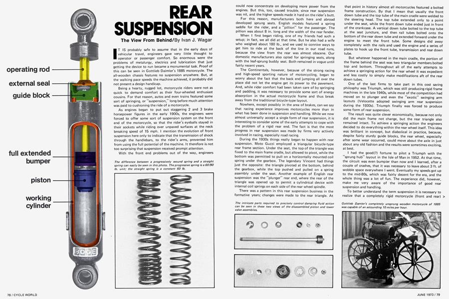
A close look at a cutaway drawing of the Boge system reveals an inner working cylinder within the damper main body. The tubing is a special seamless high grade precision extruded material imported from Germany. A sintered copper/iron guide block at the top of the working cylinder is sealed to isolate the working cylinder from the outer reservoir. There is a quality control check on every guide block to check the rod hole diameter and concentricity. Clearance between the operating rod is a mere 0.001, which provides some sealing to atmosphere even without the intricate top seal.
The top seal is a clever little device with a specially shaped top lip to keep the rod free from dirt. The lower, or internal, lip features a small coil spring around the circumference for sealing. Pressure buildup within the cylinder will also create greater sealing because of the seal's shape and construction.
Another item of material imported from Germany is the operating rod. The hefty 7/16ths rod is first cut to length, the ends threaded, and then induction heat treated for case hardening. The rods then go through four stages of centerless grinding before receiving a layer of hard chrome, then back to the centerless grinders for final lapping to size. Although the rod has the appearance of being dead smooth, there is a micro porous finish so that the seal is lubricated during operation.
The actual working piston also is made of sintered copper/iron material, and features a sintered iron piston ring from England. A flapper valve on the top of the piston controls the fluid flow through the piston on the down (compression) stroke. Different valve shapes and closing springs used during assembly determine the degree of compression damping built into the unit. On the underside of the piston there is a another valve, spring loaded to its seat, that is regulated by adjustable spring tension on a special flow jig before assembly.
Not all of the hydraulic control takes place at the piston, however. While the working cylinder is sealed from the outer reservoir at the top, it is connected hydraulically at the bottom by the "bottom valve." The bottom valve also is adjusted on a flow bench before assembly. Because of the large volume displaced by the operating rod as it intrudes into the cylinder during the compression stroke, it is necessary to provide a pressure bleed hole in the bottom valve, but that passage also is determined during valve calibration.
What all of these adjustments mean in the final product is that the Boge system permits the manufacturer to select any damping curve he feels should be employed for a particular model of damper. By changing valve seat pressures or areas, the fluid is permitted to flow, or be displaced in the system at a lesser or greater rate. It should be remembered that, while the suspension spring is sensitive to displacement, the damper unit must detect and regulate speed of travel. Providing the damper is in good working order, it cares little if it moves 1 in. or 3 in., but it cares a great deal about how quickly it is asked to move to a new position. By calibrated adjustment of the three previously mentioned valves, the Boge system is completely adjustable during manufacture at low, medium and high speeds.
The Boge unit is sophisticated, and is all the sophistication really needed? The answer is yes and no. Kenny Roberts and his friends needed a sophisticated damper system at the Astrodome short track. The pitter-patter rough surface imposed a high speed load on the dampers that could not be handled by a simple unit. Road racing is another example of where very rapid changing demands are placed on the spring/damper unit. Motocross is a mixed bag of tricks. On rolling whoop-de-doos, you can get by with marshmellows stuck between the springs; but on a washboard surface, there is no substitute for a sophisticated damper.
In tuning the suspension for your machine, regardless of the application, it is preferable to start with a good damper unit and settle for the desired spring rate after some tryout riding. The old myth that the shocks have worn out after a month and must be thrown away just doesn't hold up if the units are quality items to begin with. At Boge we tested a unit on the damper dyno (a device that sort of measures the horsepower of a damper unit) that had completed a million cycles. To achieve a million cycles it is necessary to operate at 100 cycles per minute for about a week. The units still showed no appreciable performance degradation.
It might be necessary, after starting with a good damper unit, to have a choice of two or three different spring assemblies. Keep in mind that a straight rate spring will always require a given poundage for a given deflection. The adjuster at the bottom of the damper leg will adjust the pre-load of the spring, but will not change the spring rate. In other words, if you pre-load an 80-lb. spring by half an inch it will require 40 lb. force to begin the compression cycle. A progressively wound spring, on the other hand, will require greater force to increase compression as travel becomes greater. Generally speaking, the spring that will give the softest ride without bottoming, either through lack of damper travel or because the springs are coil binding, will enable your suspension to work best. Soft springs will put less load on the damper unit, due to lower velocities and frequencies.
If the suspension bottoms out you can easily check to see if you are using up damper travel by removing the spring and measuring the damper travel. Then, if you are using a straight spring, measure the distance between coils and multiply by the number of spaces to find the stroke of the spring before coil binding. It is a little more difficult to measure the maximum permissible travel of a progressively wound spring, but it still amounts to the sum distance between all the coils. Thus, if you find that the damper unit offers 3 in. of travel, and the spring is capable of a total of 4 in., it means that the damper is bottoming ahead of the spring. This necessitates a stronger spring for that particular application.
As you can see there is no magic about shocks (a very bad Americanism to describe a damper). A good damper isa good damper, and that's all there is to the whole thing. If a damper is designed in such a way that it can be calibrated for various operating speeds, as the Boge is, it will tolerate a fairly wide variety of springs and still carry out its damping function.