The Service Department
THE SERVICE DEPARTMENT
JOHN DUNN
TORSION BAR BACKTALK
In a recent issue (CW, April '68) you described the incident of a CB-450 owner from Oregon who had a broken torsion bar. You had estimated the possible cause for this being that the factory had installed the torsion bar backward. In our opinion, the torsion bar could not have been installed backward and still run acceptably for 4000 miles. There would be serious performance problems incurred almost from the moment he rolled it off the floor.
Instead, we offer this alternative as a possible cause for the broken torsion bar: Possibly the bar broke due to a stress-corrosion crack. This, we theorize, was incurred by not changing the oil during winter months or a period of winter storage. Let me elaborate on this area. Oil can trap water in it (combustion process by-product, etc.) and retain the water in globule form. When the oil is allowed to rest on a steel surface, such as the torsion bar, for a period, such as winter storage, oxidation can and does occur. Along with the oxidation is the possibility of stresscorrosion damage, i. e., small cracks or minor surface damage. Therefore, we recommend that oil be changed on a time basis as well as mileage basis. Those motorcyclists who live in geographical areas that do necessitate winter storage would be wise to circulate, drain, and change oil every 30 days. This method would reduce the amount of stress-corrosion damage incurred by retained water and combustion by-products.
The information applies not only to Hondas, but also any engine that utilizes steel internal components.
Thos. B. Anderson Supervisor, Warranty Section American Honda Motor Co., Inc.
Thanks for your recommendations in regard to the problem encountered by Jeff W. Roberg of Portland, Ore. CYCLE WORLD is delighted to pass along your word on the broken torsion bar trouble.
MEATLESS GOLD STAR
I purchased a 1963 Gold Star six months ago. It checked out okay then, but I missed something; I never thought of checking the plug. Well, this particular KLG had a tough time coming out-and for a very good reason.
This reason prompted a Heli-Coil job. The job was done improperly. Only half of the new section is threaded. The other half is a cavity in which the plug and remaining threads of the plug are recessed.
I tried to have the job redone through another firm, but was told that there wasn’t eonugh meat left in the head for another try. Evidently, the combustion end of the hole is overly large for the standard Heli-Coil procedure.
So, what do I do? Do I have to buy another head?
Richard A. Bodell Warren, Mich.
Without making a visual inspection, it is difficult for me to voice a definite opinion as to the best solution to your problem. Your sketch indicates that a Heli-Coil insert has not been employed. Instead, it appears that an insert having a top flange has been used. The insert shown is intended for a short reach spark plug, where the Gold Star requires a long reach plug. Perhaps the only solution to the problem without resorting to the new head would be to use a short reach plug of the same heat range. The disadvantages resulting from this would be two-fold. (1) The unoccupied space below the plug would result in a reduction of the compression ratio. (2) The spark plug electrodes would be shrouded from the combustion chamber. However, an extended tip variety of spark plug would partially compensate for this adverse condition. If the short reach plug were used, very little expense would be incurred, and the plug could be removed without difficulty. All the plug threads would be protected from carbon build up.
It is almost certain that there is not sufficient material left to install a Heli-Coil of the required length, although it may be possible to have a full-length, screw-in, bronze insert made. However, if there is very little material left between the enlarged plug hole and the valve seat insert recess, this would not be practical as the head would almost certainly crack at this point.
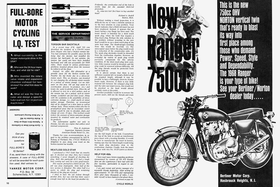
Another possibility would be to remove the present insert, drill out the threads and ream out the full length of the hole. Counterbore the top of the hole to accept an interference press insert with a locating shoulder. It would be best to manufacture the insert in bronze, making sure that the fitted length would bring the spark plug electrodes close to the combustion chamber. Finally, lock the insert in place with two No. 10-24 screws as shown.
HELP FOR 450s
I have read many letters regarding problems encountered by owners of CB 450 Hondas Here are the experiences I have had with this fine machine, particularly in regard to carbur etion.
I am part owner and service manager of a reputable Honda dealership. After setting up approximately 50 CB 450s and maintaining them after many thousands of miles, I consider myself to have learned a lot about them. During the past two years, I have ridden two, putting about 4000 miles on each. The problems which occur after this mileage mainly are oil leakages, but most problems have to do with the initial set-up of the machine before the customer receives it.
(Continued on page 14)
The object of this letter is to help owners, and possible some mechanics who are having difficulty in satisfying their customers.
First, in regard to carburetors, I refer to the 14-C model, fitted on approximately 17,000 units in the first production run. Carburetion can be adjusted to operate smoothly from consistent idle to maximum throttle opening without using the kit supplied by Honda. We have tried the kit method, but find it easier to use the standard jets and needle. The degree of modification to the carburetors varies from one machine to another, but is the same in nature. (Make sure the gas tank cap is venting properly and gas is reaching the float bowls in a steady stream.)
1.) Remove float bowls and raise the float level to the highest practical limit, which will leave about 0.125 in. of travel of the float before it hits the body. This dimension is ascertained by raising the float and noting when the float valve seats without raising the spring-loaded pin in the float valve; then the distance the float can be pushed up before hitting the body should be approximately 0.125 in. This float level is slightly higher than the manual sets forth, but it will cure the hesitation when one attempts to make a smooth getaway using low rpm. The higher float level also helps to obtain correct mixture at mid-range rpm.
2.) Remove the top of the carburetor and the piston slide. For correct operation, the slide must move freely up and down in the carburetor top, which is a double cylinder arrangement. Any drag or roughness must be eliminated completely for proper operation. On several occasions, we have found blisters or protrusions inside the smaller bore of the carburetor top. These interfered with free movement. Most 14-C models have nylon translucent inserts on the top of the small bore which allows one to hold it up to a strong light and visually inspect the surface. The material appears to be similar to a zinc die casting. These protrusions must be removed carefully to allow the chrome-plated brass insert in the slide to move up and down freely. The large diameter piston with the grooves in the outer edge does not touch the wall of the carburetor top as it moves up and down.
3.) This is the important operation to eliminate the surging caused by leanness of the mixture just as the carburetor is going from the slow speed system (slow jet and pilot jet) to the main system, which is the slide and needle. Most owners and riders are not aware of the fact that this occurs in the speed range of 55-60 mph. Only one machine worked properly without modifying the needle. The method I use to increase the fuel in this rpm range is to remove the needle from the slide and to carefully file, with a clean 0.125-in. mill bastard file, a flat section on the portion of the needle that is a straight diameter, or the top part. This is best done by holding the needle in a small modeler’s vise, and filing smoothly and accurately. The amount removed can be measured with a micrometer.
Removal of 0.005 to 0.010 in. has done the job in almost every case. Start by removing 0.005 in. of material. Reassemble carburetors and make several test rides in first and second gear. Accelerate smoothly and slowly from 3000 to 8000 rpm, noting any unevenness in operation. If there is none, you have fixed this part of the problem. If surging or roughness still occurs in the 4000 to 6000 rpm range, then more material must be filed off the needles. Do not file off large amounts, because the cross section area of the needle gets smaller very quickly. I suggest 0.001 in.; then repeat the testing procedure until the desired smoothness through the 3000 to 8000 rpm range is attained. Do this to both carburetors at the same time. Make sure that the carburetors are synchronized before starting this procedure.
(Continued on page 16)
4.) Synchronize the idle speed by feeling the strength and consistent pulse of the exhaust at the outlet of the mufflers. Then make sure that both butterfly valve arms move off idle at the same time. When adjusting the idle gas screw, turn to obtain peak revs-then unscrew about one-eighth turn.
After several thousand miles of operation, many machines develop air leakage at the top and bottom of the intake manifolds where they mate to the cylinder heads. This can be fixed by taking off the manifold and putting Permatex No. 2 or similar material on the gasket.
ALSO, after several thousand miles, oil leak ages appear here and there. The most severe source is where the leads from the alternator come through the case in a rubber grommet that has shrunk. This also can be fixed by several types of materials, such as silicone rubber, or Permatex No. 2. This source can be verified by pressurizing the engine through the breather tube; use your mouth, not an afr hose! In the case of two tubes, block off one and blow air into the other. Make sure all other engine openings are closed-oil filler cap, cam covers, drain plug, etc. Oil leakage from the front of the cylinder, where the cylinder meets the head, is due to a failure of the head gasket to properly seal because of the distance from the cylinder studs. Oil also can leak where the starter motor goes into the case. Replacement of the 0-ring usually cures this. Several of our customers have requested us to remove the top engine plates to eliminate vibration in the rpm range of 5000 to 6000. This really works! What ill effects, if any, it will have on the frame over a long period of time remains to be seen, but it surely makes the riding more enjoyable.
Archie D. Heath Thompsonville, Conn.
Although this subject has been covered before in “Service Department,” many letters directed to the column are directly related to this subject. Your comments and detailed procedure do make a lot of sense, having obviously been derived from practical experience. There are very few good experienced mechanics in this business, and your comments will be of value to the less experienced, providing care is exercised when carrying out your instructions.
A SLIPPING ACE
After having very good service from a Hodaka Ace 90, I recently traded for the newer Ace 100. The 100 runs very well, but after 250 miles the clutch went out. I have had this repaired by the local dealer and now, after only 150 miles, the clutch slips when accelerating hard. Is this a typical fault, and how can it be rectified?
A friend of mine, who has an Ace 90, and I intend to compete in some local dirt races this year. Can you please advise how we can hop up our engines so that we may compete fairly and successfully.
John Collins Wendover, Utah
A number of clutch failures have occurred on the Ace 100. It is the opinion of the manufacturer that the majority of these failures have occured as a result of abuse during the break-in period. The new clutch is built to close working tolerances and therefore requires a careful break-in period. Both friction and steel clutch plates are provided with driving teeth, which, when the clutch is disengaged, must slide freely on the matching teeth in the clutch drum and on the clutch rotor gear. Because of the close tolerance between the corresponding teeth, jamming will occur if the clutch is abused during the first few miles of operation. This will result in the entire load being applied to one friction disc, causing the teeth to strip because of the overload.
It is recommended that a break-in procedure be adopted before the machine is ridden. With the engine running, and the clutch disengaged, select low gear, then “cycle” the clutch at least 50 times (release the clutch until it is just starting to pull, then fully disengage). Repeating this procedure will allow the teeth to slide back and forth, thereby adequately bedding in the working surfaces. Be careful not to overheat the clutch, as this will result in permanent damage. After carrying out this procedure, check that the clutch lever has the correct free play. During the first 150 miles of riding, do not abuse the clutch with excessive loads, being particularly gentle when making down shifts.
Your second problem related to clutch slip is not a result of the previously mentioned malfunction. This problem is caused by insufficient spring pressure resulting in clutch slip when the clutch is highly loaded, as when accelerating hard or making slick gear changes. Dismantle the clutch and install clutch inner springs (part No. 904017) from the earlier type clutch, in addition to the single outer springs already fitted. While the clutch is dismantled, check that the clutch hub is a nice sliding fit in the clutch cage. If not, carefully ease the teeth with a smooth file until they slide freely.
(Continued on page 18)
There is a factory high compression cylinder head having a 12:1 compression ratio, which is intended only for competition purposes. This head can be used on either the 90 or the 100 model. A racing piston with a single Dykes type ring also is available to suit the 50-mm bore of the standard Ace 100. The 90 also can be bored oversize to accept this piston, but it is recommended that standard 100 piston pin (part No. 922707) be used. Part No. of the piston is 9301500 and the Dykes ring is part No. 9302500. A race-tuned exhaust system of the expansion chamber type also is available from the factory. The higher compression ratio definitely will require the use of a colder spark plug. I would suggest starting with a B10 or equivalent.
The higher ratio and race exhaust system will make it necessary to go richer on the fuel. Starting with the main jet, go richer until the engine misfires at full throttle; then fit a jet one size smaller. Also, raise the throttle needle until misfiring occurs on acceleration; then lower it one notch.
HOW MUCH OIL?
I have installed Circle Industries’ heavy duty springs in the fork of my Hodaka. I weigh 200 lb., so what weight oil, and how much of it, does the fork need?
Arnold Freidig Fond Du Lac, Ms.
Use the maker’s standard recommended grade and quality of oil. Hodaka recommends that each fork be completely drained, and then refilled with 4.5 oz. of oil mixed in the following proportions: 60 percent SAE 80 W gear oil and 40 percent SAE 30 W non-detergent engine oil with an MM service rating.
Over-filling will cause oil seal failure. The recommended grade of oil is of very high viscosity, so if the fork still tends to bottom, try an 80 percent/20 percent blend. If you have no means of measuring the correct quantity, a dipstick can be made from a length of welding wire, 0.062 or 0.125 in. in diameter. The correct oil level from the top of the fork top crown should be 12.75 in.