Ignition Systems
IGNITION SYSTEMS
GORDON H. JENNINGS
THE BASIC WORKINGS of a simple, single-cylinder engine can be easily understood because they can be seen. Anyone of average intelligence can look at an engine's various parts, and watch them go through their motions as the engine is cranked slowly over, and soon arrive at a reasonably clear understanding of what is happening and why. This is, in point of fact, precisely the way in which most of us acquire our early training in the mysteries of the internal combustion engine.
Unfortunately, there is one item of related hardware that does not explain itself at all well: the engine's ignition system. There, few of the parts move; most of the activity is in the ebb and flow of electricity and magnetic waves, and those are of course invisible. No one can see what is happening, and few people have more than a rather foggy notion about the nature of the processes that culminate in a spark at the engine's plug. In the most practical terms, this lack of understanding would be acceptable, except that unless there is a spark tl)e engine will not run, and ignition malfunctions are still by far the most common of the problems encountered by motorcyclists. If we are to be able to consistently find and correct these ignition system troubles, we must have a good working knowledge of how each type of system now in use produces that small, exceedingly important spark.
Today's ignition systems take many different forms, but they all have one thing in common: the use of the phenomenon of inductance. Back in 1831, Michael Faraday discovered that moving a wire through a magnetic field would induce (hence the term, "inductance") electricity in the wire. Similarly, a flow of electricity in a wire would induce a magnetic field around the wire. In both cases, the effect was increased by lengthening the wire, increasing the magnetic field strength, and increasing the speed of the wire through the magnetic field.
This scientific curiosity has a practical application in the ignition "coil," which uses both the electricity-tomagnetism and magnetism-to-electricity components of the phenomenon of inductance. A coil consists of a soft iron core around which is wound two separate sections of insulated wire, one over the other. The inner section is called the primary winding, and when it is connected to an electrical source, such as a battery, a magnetic field is induced. The purpose of the iron core is to gather and align the lines of force, which has the effect of strengthening the magnetic field. A special soft iron is used for the core because it is a good "conductor" (for lack of a better word) of magnetism, but does not remain magnetized after the electricity is switched off.
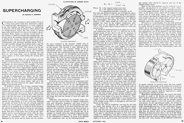
The coil's secondary, or high-tension windings are not connected, in any direct sense, to the primary windings. But, obviously, the secondary coil is very active indeed, as it is the source of the spark (which is many thousands of volts in intensity) that fires the engine's mixture. Let us examine how this occurs. In the circuit between the battery, coil and "ground," there is a set of breaker points (a switch) which is actuated by an engine-driven cam. We start the process with the point block riding on the heel of the cam, with the points closed and current flowing to the coil's primary windings. This means that there is a strong magnetic field around the coil and, as the current flow and voltage are substantially steady, the field is pot moving. In this condition, the coil may be regarded as "ready." Then, when a spark is required, the cam pushes the points open and the flow of current is interrupted, which results in the rapid collapse of the magnetic field. As the field collapses, its lines of force drop inward through the coil's windings, and as they do so, an electromotive force of very high voltage is induced in the coil's secondary windings and that creates the spark at the plug (assuming, of course that the spark lead is intact).
All very simple isn't it? No, it quite obviously is not! The very clever reader will want to know why there is no spark from the secondary when the points close, as the magnetic field must push outward through the secondary windings as it is created by the primary. What happens is that when the points close, and current is directed into the primary, the field builds too slowly to induce much voltage in the secondary. You see, when the primary is turned on and the magnetic field starts to build, the outward moving lines of force must first push through the primary winding, and this action tries to induce a current flow in the windings that is of opposite polarity to that flowing from the battery. The result is that the buildup of the magnetic field is self-damping, and much more time is required for the field to build outward, than to collapse back in. Consequently, although some electricity will be induced in the secondary when the points close, the real blast does not occur until the points open and we have that very rapid field collapse.
Now we come to the condenser. If you have been following closely all this business about field collapse and inductance, you must surely realize that the rapid collapse of the coil's field must induce electricity in the primary as well as the secondary. However, the primary has but a fraction of the number of turns of wire as the secondary, and the induced voltage is much lower. Even so, there would be more than ample voltage to push a spark across the just-opened points were it not for the action of the condenser. To understand the nature of the condenser, one should know that its proper name is "capacitor," and that is a much more descriptive word. Electricity behaves in many respects (at least on the level that concerns us) like a gas, and we may consider that voltage is pressure, and amperage, or current, is the rate of flow. Now then, if a condenser is inserted in a circuit, current will flow into the condenser, and voltage in the circuit will drop, until the condenser is "full." The larger the condenser, the more electricity it will "store."
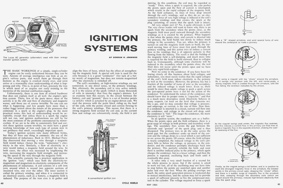
In an ignition system, the condenser acts as a buffer. When the points open and the field collapses, there is a great surge of voltage in both primary and secondary windings. The secondary fires across the gap between the electrode and "ground" of the spark plug, and is thus dissipated. The primary tries to do the same across the point gap, but the condenser soaks up much of the current and the voltage drops to a level which is not sufficient to arc across the points. Of course, when the field collapse is nearly completed, the induced voltage in the coil's primary falls to below the voltage, or pressure, in the condenser, and the condenser promptly discharges back into the primary. This partially rebuilds the field, and soon there is another induced pulse in the primary, which again charges the condenser, but to a lesser voltage, and then the process is repeated, oscillating back and forth until it eventually dies away.
It takes only a very small fraction of a second for the whole process to occur, but if the system is asked to work too fast, all of the oscillating may not have time to stop before the points are snatched open and another pulse laid over the first. When the pulsing overlaps too much, the entire spark generation process is weakened due to mutual interference, and the system may fail to provide a spark of sufficient intensity to fire the compressed mixture in the cylinder. The voltage required to force a spark across a gap is increased as pressure increases, and a system that will fire satisfactorily at atmospheric pressure may not even flicker in air compressed to, say, 100 psi. Incidentally, any spark that is strong enough to fire the engine's air/fuel mixture at all is strong enough for maximum power. There is no such thing as a weak spark weakening power output unless the spark is so weak that misfiring occurs.
Apart from functional problems, such as a bad coil or condenser, or badly pitted points, the most common failing of a battery and coil ignition system is that at very high speeds, the points may not remain closed long enough to build up a good, strong magnetic field before the points are re-opened. This is an especially likely problem in highrevving two-stroke twins, which require sparks at twice the rate of a four-stroke twin. The way to overcome this is to provide an ignition system that delivers such a hot spark that even when the system fades at high speeds there is enough voltage to do the job. Problems may also be encountered with point "float" at high speeds. If the breaker cam is twirled fast enough, the spring on the points may not be able to pull them shut quickly enough to take full advantage of the "closed" period. The closed period is much reduced when a single set of points and a single coil is asked to fire two cylinders, and this is one reason why in the latest designs dual points and coils are used to fire twins. The other reason is that the dual points eliminate the bulky and potentially troublesome distributor rotor and cap.
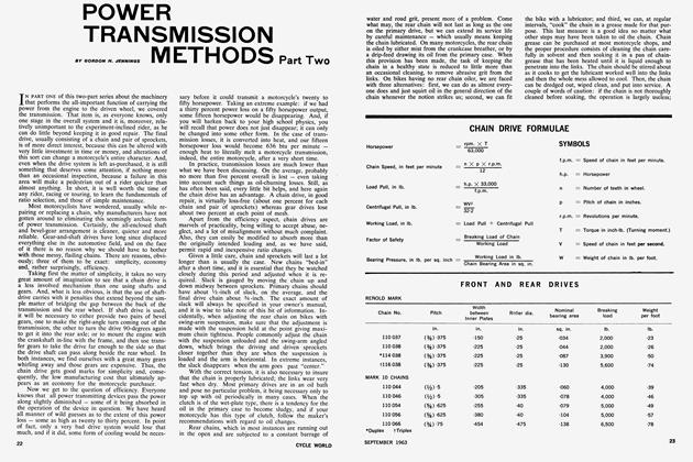
Magnetos use the same principles of inductance as the battery and coil system, but in a much different way. "Flywheel" magnetos (which differ only in detail from the other type) are very popular today, so we may as well start with them. Most have a fairly large flywheel, the rim of which houses one or more permanent magnet s, surrounding a set of coils, which are wound around an armature. As the flywheel rotates, it sweeps past the coil and the field from its magnet is picked up briefly by the coil armature. This creates a magnetic field around the coil, and as this field builds, induction creates a flow of current in the primary and secondary sections of the coil. However, in the case of the magneto, the primary is wound so that as electricity is induced in it, it promptly creates a magnetic flux that counters and to a great extent cancels that from the flywheel magnet. Thus, nothing much can happen in the secondary (high-tension) windings at that point. But, as the flywheel magnet moves to the position where its field is acting most strongly on the coil, a cam pushes open a set of breaker points and the flow of induced current in the primary is interrupted. This permits the flywheel magnet to send a surge of magnetic flux through the coil, which induces a high voltage in the secondary windings, and that in turn provides the spark for the engine's plug. A condenser is provided, in "parallel" with the points, and it serves the same function as in a battery and coil ignition system.
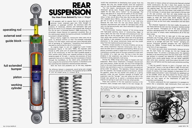
Early versions of the flywheel magneto had a nearly straight armature, with ends shaped so that they could run in close proximity to the flywheel, and indeed many are still made that way. However, it has proven possible to make the unit more compact by using a "W" shaped armature, with the coil wound around the center portion. In magnetos of this type, which are used extensively in small "kart" engines, the magnetic field is first fed through the first and center "uprights" of the W, and then as the magnet in the flywheel swings a bit farther, the field reverses suddenly and that makes the magnetic flux move through the coil very fast. The secondary windings resist this briefly, and then the contact breaker opens, killing the holding effect of the primary, after which the full force of the magnetic flux hits the secondary windings and high
voltage electricity is induced. This type of coil and armature arrangement lend themselves particularly well to the layout where the magnet is small in diameter and located inside the coil and armature, rather than the other way around, as is usually the case in motorcycles.
Most of the magnetos made for four-stroke engines are far removed from the flywheel. Usually, they are mounted behind the cylinder block, over the back of the crankcase, and are driven by either chain or gears at half engine speed. Still, the operating principles are substantially the same. In old style magnetos, the magnets were mounted in the casing and primary and secondary windings were in a rotating armature. However, as engine speeds increased, the magneto armature began to reach the sort of rotational speeds where centrifugal force would pull its windings apart. To counter this, the latest type of racing magneto was developed, which has rotating magnets and fixed coils. In both of the above described magnetos, there is a set of breaker points, and both use reversing magnetic flux to induce high-tension electricity in their secondary windings. The new type magneto has the additional advantage of not requiring a slip-ring and carbon brush to transmit the high-tension electricity to the spark lead. Neither does it require a brush and slip ring to link the primary windings and the breaker points.
Incidentally, in the old-style rotating windings magneto, the slip ring for the high-tension brush has a couple of "ground' screws positioned near it in the magneto case. These are provided to protect the windings in the event that the spark lead becomes detached. If the secondary is not allowed to discharge across a relatively small gap, as at the spark plug, voltage in the secondary windings may build to such a level that it will arc across to the armature, burning a hole in its insulation in the process. The ground screws give the electricity some place to go (apart from burning through the insulation) if the voltage gets too high.
While on this subject, we might as well issue a warning to those who are fond of clearing a fouled plug (on a twin) by pulling off the plug lead and allowing the spark to snap across a wide gap to the electrode end of the plug. This will clear the plug, as it forces the voltage to rise enormously before the plug is fired, and that will often burn away a little oil or a carbon whisker. Unfortunately, it also pushes the coil voltage up far enough to burn through the insulation inside the coil.
The "energy transfer" ignition system is also very popular these days, and there is a great deal to recommend this kind of system. It is, simply, a conventional system with an AC generator (usually called an "alternator") instead of a battery. But, unlike a battery powered ignition system, the ignition timing cannot be moved around with complete freedom. In the energy transfer system, there is a rotating magnet at one end of the engine's crankshaft, and this magnet is surrounded by windings. As the engine runs, the magnetic flux sweeps through the windings, and alternating current is generated. As you know (or at least should know) alternating current does not flow steadily, as is the case with direct current. It rises to peak voltage, then falls off to zero and rises again, but with opposite polarity. In the energy transfer system, the points must be set so that they open at precisely the moment when the voltage from the alternator reaches full strength. On engines having energy transfer ignition systems, it is necessary to time both breaker point opening and the alternator, and if one fails to do this properly, a weak spark will result. Potentially, energy transfer ignition is the most efficient and least troublesome of all the various types in existence today. In practice, lack of understanding on the part of owners and mechanics, and a certain indifference by manufacturers to the necessity for quality control have made energy transfer ignition something regarded with extreme suspicion by many motorcyclists. Even so, this type has too much in its favor not to come into wider use, so we may as well learn how to work with it.
In addition to the better known ignitions, there are some interesting and quite promising systems being developed. The one that has received the most attention in recent years is "transistorized" ignition. A lot of nonsense has been spread around with regard to the transistor, but the plain truth is that this tiny bit of hardware is just another form of switch. Its primary value is that it does the switching without the benefit of moving parts, and it can be made to handle a great deal of current. As applied to ignition systems, the transistors are used to "valve" current to the coil. The conventional points serve only as a trigger to control the transistor. This places a very light load on the points, and they will last almost indefinitely. Also, the transistor switches the current on and off so quickly that, in effect, the system has more time in which to do its work. There is one additional benefit, too, and we will get to that one shortly.
Wico-Pacy, in England, has developed an ignition system that may eventually become standard equipment for all two-strokes. They have a sort of flywheel magneto in which a small rectifier (an electronic one-way valve) holds stored in a condenser the electricity from a generator coil inside the flywheel. When a spark is needed, the breaker points close (the reverse of the conventional system) and the condenser discharges through the coil's primary winding to ground. This surge of current in the primary creates a magnetic field almost instantly, and that induces the customary high-tension electricity in the secondary. The system's output voltage is not much, if any, higher than that of a conventional system; what makes this departure from the conventional worth the effort is that the voltage in the secondary rises to full value in much less time than in other systems. In fact, the full jolt is delivered to the plug so quickly that even if the plug is wet on the outside, or covered with oil on the inside, there will still be a spark arcing across the plug gap. With slower voltage rise, much of the voltage may have time to leak away without firing the plug; in this condenser-discharge system, the voltage leaps up so quickly that there is not time for it to dribble away before it is forced to jump the gap between the plug's electrode and ground. The transistorized system we just finished discussing has the same valuable characteristic.
A final off-beat system we would like to mention is one developed here in America: the piezoelectric ignition system. Some time ago, it was discovered that certain crystalline materials would, if stressed, develop an electrical charge. Eventually, a ceramic called lead-zirconatetitanate was created, with high piezoelectric properties and great strength. This ceramic was just the thing to use in an ignition system, and that is precisely what has been done. The Clevite Corporation now has a device they call a "spark pump" that is being used on chain-saw engines, etc. In this device, a pair of rods made of the ceramic are fixed under a small lever, and when the end of the lever is loaded to 80 pounds, the ceramic rods develop 16,00019,000 volts, which is ample to fire a spark plug. In application, the lever's end rides against a cam, and when the lobe of the cam swings around, it gets its 80-pound loading and bang, there is a spark. At least, this was all there was to it in early prototype systems. Later, it was found that the sudden stressing of the systems created excessive wear of the impacting parts, and a lot of noise. Hence, later production versions had levers running against an eccentric, so that the loading was applied gradually. Then, to get the quick voltage rise required, a sort of distributor rotor and cap was added. In this form, pressure and voltage at the ceramic rods builds gradually and then, as the spark is needed, a rotor swings into position next to a couple of contacts (without actually touching them) and the voltage from the rods is discharged out one contact, across the rotor, and then to the other contact, to which is attached the lead to the spark plug.
The most valuable characteristics of the piezoelectric system are: that it develops full voltage at a very low cranking speed (which means easy starting); and that it is very light and compact. Also, with the "distributor" added, it gives a tremendously high effective rate of voltage rise, and will fire plugs that with almost any other system would be considered "fouled." Its main disadvantage is that there is a comparatively long recoverytime required after each pulse, and that renders it unsuitable for very high-revving singles and twins.
And what is the best system of them all? Frankly, we are not at all certain. On the basis of sheer output, the transistorized system Lucas makes for Grand Prix racing cars is something of a champion. This system uses a magnetic trigger, instead of breaker points, to control its transistors, and it will deliver more than 60,000 sparks per minute, each of them over 20,000 volts in intensity. Of course, this system is quite expensive, and it is fed from a battery, which on a racing bike is best eliminated if possible. Actually, few motorcycles make very heavy demands on an ignition system, and any system in good condition will do the job. Many racing bikes use a battery and coil system, and this works extremely well unless the battery fails, due to either simple exhaustion or from vibration breaking its plates. There are also a lot of bikes using energy transfer systems, and here again the job is done properly unless something fails. Magnetos? They work too, provided there is not internal shorting or a condenser failure. Our personal feeling is that the energy transfer system will, over the next few years, become virtually standard on all bikes; racing or otherwise. This type system, with its external coils, is more easily accommodated than the bulky magneto, and it shares with the magneto the freedom from needing a battery. And, obviously, tomorrow morning, we may sort through the mail and find that someone has developed an entirely new ignition system that will render the ones we have been discussing entirely obsolete. •