(technicalities)

(TECHNICALITIES)
GORDON H. JENNINGS
ONE OF THE HUNOS that appears to be of enduring interest to the CYCLE WORLD reader is the rotary valve 4-stroke engine. We always seem to get a few letters asking about rotary valves in general or some rotary valve engine in particular. As a matter of fact, there have been many such engines, and in all likelihood we shall he seeing more of them in the future — although for what reason I cannot imagine. The poppet valve, despite its more obvious shortcomings, does a marvelous job.
In general, it may be said that the only advantage of the rotary valve layout (in four-stroke engines) is that it permits a slightly higher compression ratio than the poppet valve system. An exhaust poppet vahe runs red hot, literally, when the engine is operating under conditions of full-throttle and full load, and it provides a hot-spot in the combustion chamber that very substantially increases the risk of detonation. By contrast, the rotary valve is relatively cool (of necessity) and unless the combustion chamber is very badly shaped, a higher compression ratio can be employed than would be possible with poppet valves.
Most people seem to have the idea that the rotary valve layout has some great advantage in terms of volumetric efficiency. This would he wonderful if it w'ere
only true. In point of fact, the breathing capacity of the rotary valve system is quite likely to be inferior to that of poppet valves. Because the valve rotates at half engine speed, its rate of opening is quite small, and for the same nominal valve timing as one would find in a comparable (i.e. racing or touring) poppet valve layout, one will find that the rotary valve’s open área, plotted against crank rotation, is not very impressive. One should not forget that except for the short time when the valve is centered on the seat, the edge of the valving element shrouds part of the port opening, and shrouds it in such a way that airflow is very considerably upset. If there were some way of increasing the diameter of the rotating element, then there would be enough area along the rim of the valve element to provide an increased period when the port was completely unshrouded, but that is not practical — due to considerations of space.
Rotary valves, fitted to the crankcases of two-stroke engines, do work well, but they do so because there is room to make the valve disc quite large, and because they are driven at engine speed, which makes the opening and closing of the valve more rapid. If you will examine the disc from a two-stroke rotary valve, you will find that the cutaway along the disc's rim is very much larger than the port it controls,
(Continued on Page 20)
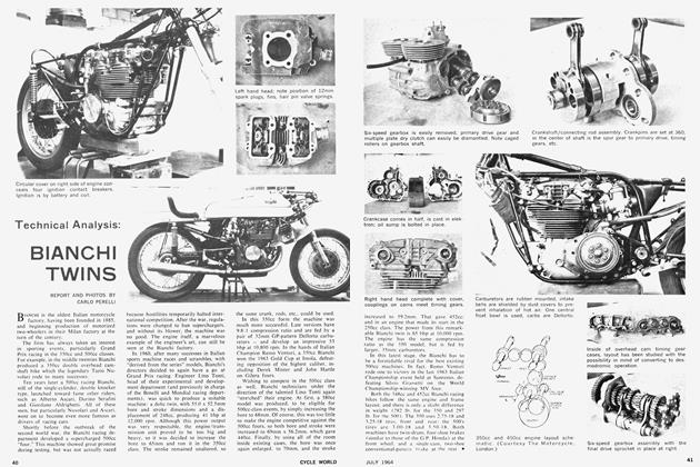
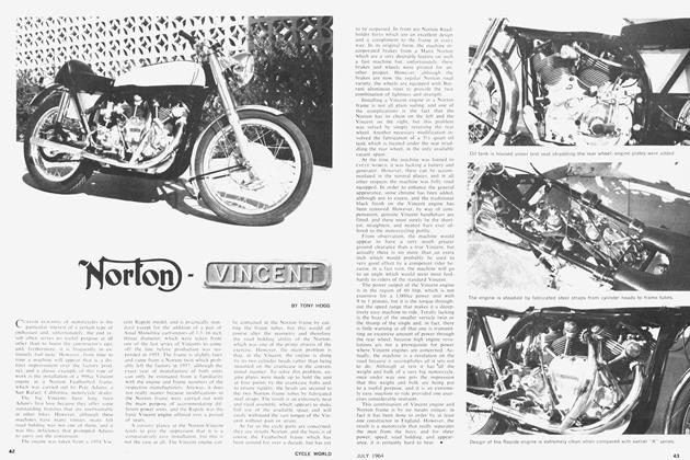
The Aspin sleeve valve engine.
so the port is completely unobstructed through many degrees of valve disc rotation. Thus, the crankcase rotary valve of the two-stroke engine is very effective, and we may expect to see a more widespread use of this form of intake valving. One of the few rotary valve four-strokes to reach production status in a motorcycle was the C ross engine. I he Cross engine had a cylindrical valve set in its cylinder head, and the valve contained passages that connected with a carburetor at one end, and with the exhaust pipe at the other. There was. of course, also a blank side to the valve's rotating cylinder that sealed the tip of the .combustion chamber during the compression and power strokes. To overcome sealing problems at the valve, the entire cylinder was allowed to float slightly, and gas pressure would force it up tightly against the valve, which was tied to the crankcase with long bolts. This method did provide reasonablv good sealing, when the engine was relatively new. but wear was a problem. To combat wear, oil was fed the valve under pressure, and as a consequence oil consumption was quite heavy. As development work on the Cross engine progressed, it became apparent that its makers would have to make a choice between heavv wear of the valve, or heavy oil consumption, and they chose the latter. Others who have tried to make the rotary valve work have all been eventually forced to make the same choice.
Another rotary valve layout was the one used in the Aspin engine. In this, the cylinder head contained a conical rotating element, with an axis common with the cylinder. The head had intake and exhaust ports that were alternately covered and uncovered by a cutaway in the valve cone, and that is how the valving was accomplished. This engine ran. and rather well, but again there was no gain over the poppet valve system and again there was a wear problem that was overcome only by supplying copious quantities of oil.
NSU tried a disc-type rotary valve in an experimental racing engine, and while it is probably the most promising of the lot. it showed no clear gain over a similar poppet valve engine. In the NSU design, the valve disc was quite large in diameter, and was both angled and offset relative to the cylinder bore axis. This was done to improve cooling around the valve, and to give the best possible combustion chamber shape. Again, vast amounts of oil were required, and even with that wearing of the seals was rapid. Also, it was found necessary to provide a large flow of oil through the valve body to give adequate cooling.
These examples, none of which came to much success, by no means absolutely rule out all possibility of a workable rotary valve system for the four-stroke engine. Our technology, particularly in the (Continued on Page 22) field of metallurgy, is advancing rapidly, and one never knows when there will be the breakthrough that will make the rotary valve a practical proposition. However, if this does occur, and the rotary valve fourstroke comes into widespread use. it will not be because of better breathing capabilities. but because the rotary valve offers the chance of slightly higher compression ratios, and because it will make the engine smoother and more silent.
SUPERCHARGING
Supercharging was once a popular method of getting a full gallon of performance out of the proverbial pint pot. but it has fallen into disuse in recent years. Still, it has its attractive features, and is in most respects an easier way of boosting the output of some particular engine than the more common expedient of boring and stroking to the maximum. Increases in bore or stroke always mean increased inertia loadings LUI the engine's vital crank train, and of course that does nothing at all for reliability. Also, except m a few engines, it is not possible to increase the displacement to any great extent without constructing a new crankcase and crankshaft, or a new cylinder and piston, or all of the things listed. Obviously. all of this becomes expensive.
On the other hand, when fitting a supercharger it may not be necessary to go into the engine at all. A new intake manifold and some sort of mounting and drive may be all that is required. However, whatever changes are required the supercharger will make it all very much worthwhile. If. for example, you pump the mixture in at 7.5 psi over atmospheric, you will he adding, in effect. 50-percent to the engine's displacement. In other words, a 50()cc engine, supercharged to 7.5 psi. would become a 750: the same relationship would apply to other engines, too.
(Continued on Page 58)
Obviously, there are some problems connected with supercharging. First, it is not always easy to find room for a supercarger in a spot where rigging a drive w'ill not be too big a problem. The most simple and direct layout would be with the “blower" driven directly from the end of the crankshaft, hut (with the exception of the BMW) that would put the thing in a rather exposed position, hanging out on the side of the machine. Locating the blower in front of the engine, and driving it through a short chain or belt drive will also work. but there is not room on most motorcycles for that positioning and in any case, that would require very long manifold pipes, and such pipes virtually guarantee poor low speed running and difficult starting. The best spot for the blower is right up against the hack of the engine, where the delivery pipes from the blower to the ports can be kept short.
In designing the manifolding between the blower and the ports, a fairly large chamber (with a volume at least as great as the displacement of one of the engine's cylinders) should be provided. The reason for this is that there is not a steady flow of mixture into the cylinders), and the delivery from all but centrifugal superchargers fluctuates. Therefore, you will need the chamber in the manifold to dampen the pressure variations.
For boost pressures much above 6 psi. it will be necessary to modify the engine somewhat. This is particularly true if the engine being fitted with a blower has a compression ratio much above 8.0:1. We Americans arc fortunate in having available very high octane-rated fuels, in the premium grades, so it will be possible to use moderately high boost pressure in conjunction with compression ratios circa 8:1 without encountering detonation. But. if you really want the ultimate, with a boost of perhaps 15 psi. the compression ratio will have to be lowered.
Quite probably, the best place for a supercharger is on a road machine, because that would give a very substantial boost in performance without recourse to exotic fuels, and without affecting low speed running. The job is. obviously, not an easy one, and the pitfalls are many, hut the results could (if all goes well) more than justify the bother. Actually, the whole subject of supercharging, as related to the motorcycle, deserves a more elaborate treatment than it has been given here, and it occurs to me that it might make a good full-scale technical article. I promise that such an article will be forthcoming very soon. •