Frames & Suspension
FRAMES & SUSPENSION
Part two: elements of design and construction
GORDON H. JENNINGS
HAVING COVERED, in tiresome detail, the theoretical aspects of frame and suspension design in last month’s opening article on the subject, we are now ready to proceed into a discussion of more immediate usefulness: the elements of actually designing and constructing an original creation. And why, one might logically ask, would anyone want to do such a thing? We’re not at all certain that there really is a reason, except for the entertainment value of a really far-out do-it-yourself project and whatever satisfaction one gets from viewing the finished product. Certainly, it would be difficult (if not impossible) to better the efforts of the manufacturers. The only time this is possible (with a few exceptions) is when you are building for a very specialized purpose, such as road-racing, scrambles, etc. For the pure single-purpose machine, the many restrictions (cost, reliability, practicality, et al) that force manufacturers to compromise their bikes, no longer apply. When such is the case, the individual constructer may very well be able to beat the factories.
To a great extent, the general layout of whatever frame is being designed will depend on the engine and transmission being used. When these components are in a single casing, and have cast-on lugs that enable them to be used as structural members (as in the Honda) or mounted in a suspended or cantilevered fashion underneath the frame (NSU, H-D Sprint, Suzuki), a single-
member, spine-type frame is very attractive. However, in most instances, it will be necessary to cradle the engine in a sort of sling, with the ends turned up and connected to the steering head and the rear suspension unit mountings. Loads from the steering head should be spread across the top of the frame.
Other loads to be designed for are those that would deflect the frame laterally, and twist it. Insofar as beam strength is concerned, we could cut the frame outline (side view) from flat steel plate, and there would be plenty of resistance to vertical loads. However, such a frame would bend to the side or twist very easily, and we must, therefore, give the frame widtli, as well as depth. This can be accomplished by making the frame a loop of steel tubing, in which case the tubing’s resistance to bending and twisting will constitute the frame’s capacity in that respect.
At this point, it might be wise to state a few simple truths about the properties of steel and of structural shapes, tubing being one such shape. Tubing’s strength to weight ratio is highest when the wall thickness is at a minimum and the diameter is greatest. Moreover, strength increases much faster than weight (at the same wall thickness) with increases in diameter: at the same weight, a single large tube is much stronger than a pair of smaller tubes. Other structural shapes, channel-sections, I-beams and the like, cannot match the torsional strength of the tube, but there are instances where, for example, an Ibeam can be used to good effect to carry a beam loading just because so much of its material can be disposed directly along a load path. Even so, a hollow rectangularsection member can have (at the same weight) equal or better beam strength and it will have a greater measure of torsional strength in the bargain. Thus, there are compelling reasons for using thin-wall round, square or rectangular-section tubular frame members.
The selection of materials is a straightforward job; given a few simple ground rules to follow. Ordinary mild (low carbon) steel is most often used, and it is all too often scorned by the back-yard builder, who generally has some mystic attachment to “chrome-moly.” Actually, supertough alloy steels have their uses, but they should be restricted to very special applications. As we have been saying (unto weariness), the basic property that we are trying to build into a frame is rigidity. A frame that is rigid enough will, in almost every instance, have more than enough strength to preclude bending or breaking. And, if the frame is rigid, then the fatigue-resistant qualities of chrome-molybdenum steel are of no value. After all, the modulus of rigidity of a mild-steel tube are the same as those of chrome-moly; only the ultimate yield strength differs.
Aluminum offers no solution, either. Aluminum is only 1/3 as heavy as steel, but it is also only 1/3 as strong. Thus, an aluminum structure (because three-times the amount of material has to be used to give the same strength as steel) will, in the end, offer no advantage.
Actually, certain types of structures do allow weightsavings through the use of exotic steel or aluminum alloys, but these present such difficult fabrication problems, and are so expensive, that they are quite beyond the amateur builder. For all practical purposes, mild steel is the best material for the job. For the amount of steel actually involved, we could use chrome-moly — just to make the frame more crash-resistant — but such alloys are difficult to weld or braze safely because of local embrittlement at the welded joints. The only solution is to have the frame heli-arc welded and then pop the whole thing into a heat-treating oven to relieve these local brittle spots. Another possibility, which also involves the use of an oven, is to pin the frame tubes in their proper positions, put a brazing paste on the joints, and then bring the whole assembly up to the melting temperature of the brazing alloy. This is called “furnace brazing;” it is an excellent technique, and is widely used by motorcycle manufacturers, but is out of the question for most special builders. The necessary facilities are just not available in most areas. High carbon steels, which are very strong (although having no better rigidity than any other steel), can be heat-treated to eliminate brittleness at the joints, but in so doing, much of the strength produced by the “workhardening” of the tubing, produced in the “drawing” operation that is used in making the tubing, is lost. In the end, the only attraction of special alloys, such as chromemoly, is to allow the use of large diameter tubes (for the reasons we have already outlined) with ultra-thin walls. There, the high yield-point alloys prevent local denting and buckling of the tubes.
When thin-wall tubing is used, we encounter yet another problem: the stress concentrations that loading the frame creates at its joints produce heavy local loads and the frame may fail. There are two solutions to this: first, we can add gussets at all corners to spread the loads more evenly at the joints; second, the frame can be designed so that the tubes are loaded only in tension, compression and torsion and carry no bending loads. In practice, seldom will we ever be able to achieve this second condition, but there are compelling reasons for trying. A length of tubing may easily be bent across one’s knee, but not even a strong-man can stretch it, collapse it endon or twist it. Obviously then, it is strongest when bending loads are avoided.
One final note about welding and brazing: when one possesses, or can beg or hire, an exceptionally skilled welder, it is possible to combine the use of chrome-moly steels with nickel-bronze or manganese-bronze welding for a superior finished structure. These welding alloys can be flowed on at a temperature just slightly lower than ordinary welding (which involves the melting of the primary material) requires, and it gives a high-strength joint without affecting the steel unduly. However, too much heat will cause the welding rod to penetrate the steel and weaken the joint and too little will leave the weld fillet in a poor bond with the steel and a weak joint will again be the result. For all of these reasons, we recommend ordinary mild-steel most highly. For the builder who simply must go everyone a step better, there is always manganese steel, which welds particularly well and retains most of its original strength after welding. Still, if the frame has been designed with sufficient care, high-grade steels will offer improvements only in damage resistance; you will be less likely to be put to the job of building a new frame as the result of a hard fall.
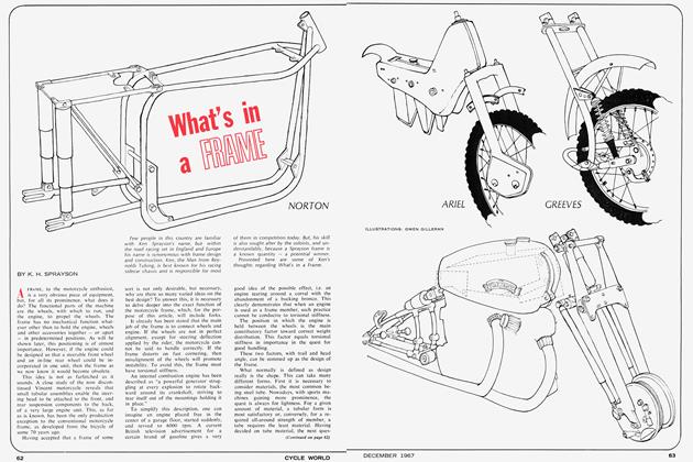
Assuming that you now know what material to use (an unlikely state of mind after all this discussion), the next step is to lay out a frame. Ideally, the frame would consist of a series of tetrahedrons, which is a form well suited to resisting torsion, compression and tension loads, but inasmuch as the various mechanical elements tend to get in the way, we will have to depart considerably from this ideal. Indeed, the most practical frame layouts have no relationship at all to the tetrahedron. The least involved and most inexpensive frame layout is the single-loop type, which has a single tubular member leading down from the steering head, under the engine and transmission, and back over the top to connect once again with the steering head. This configuration is simple, but it places the tube under heavy bending loads; for which it is well suited in a vertical plane. Bending loads from the side, however, must be taken by the pure beam strength of the tubing, and a tube is not very efficient in that respect. Also, with a single loop, there must be a lot of gusseting around the steering head and separate brackets for engine and transmission mountings — not to mention the outriggers that straddle the rear wheel and carry the spring/damper units. Therefore, the simplicity of the single-loop frame is countered by a considerable penalty in weight.
A much more desirable variation on the basic singleloop frame may be employed when the engine and transmission can function as part of the structure, or hang, cantilevered, under the frame. In such cases, the frame can be a single tube, leading from the steering head to the rear suspension pivot. Several excellent motorcycles have frames of this general type: the Honda is one; the Harley-Davidson Sprint another; and the 250 Ducati has a design that falls about midway between the back-bone tube, and single-loop layout. Whenever the engine selected as a starting-point for a special will allow a single-tube frame, it is wise to make use of it. After the outriggers necessary for mounting the spring/damper units are added, it will be slightly heavier than the best examples of a multi-tube frame, but it offers the best opportunities for a very short building time and uncommonly good damage resistance. Engines with the cylinder(s) jutting forward, as in the H-D Sprint, are rare, but they allow a frame that is just a single tube, running downward from the steering head to the swing-arm pivot. In the more usual layout, where the cylinders(s) are vertical, it will be necessary to put a bend in the tube — probably about 75-80 degrees. The use of a Honda engine, which can be made to double as part of the structure, will require a couple of additional tubes to bridge between the ends of the main tube and the engine/transmission package. Obviously, in this layout, the main tube may be made slightly lighter while maintaining the same overall strength.
The conventional two-loop frame actually has two tubes only along the bottom of the structure. These lower tubes serve to cradle the engine and transmission, and the arrangement is particularly well suited to the task when the transmission must be mounted separately. In all instances, the two widely-spaced tubes add greatly to the lateral rigidity of the frame, and they are almost indispensable when a large, powerful engine, which imposes heavy torque and weight loads, is contemplated. It is no mere accident that most — indeed, virtually all — bigengined bikes have frames of this type.
The best example of the “true” two-loop frame, and indeed the only example currently in production, is to be seen on the big Nortons. They all use, in one form or another, the famous “Featherbed” frame developed by Norton for their racing model, the Manx. This frame has a pair of tubes that start and end at the steering head and, on their way around, cradle the engine and transmission. It is a layout that has been copied by almost everyone, in some form or another; even the Honda fours, in their latest form, have what is virtually a copy of the Featherbed frame. True, the Honda’s frame does not make the complete loop; the engine/transmission unit takes the place of the lower sections of tubing, but the detail around the upper part of the frame — particularly in the area of the steering head — leaves no doubt as to where Honda’s engineers drew their inspiration. If we may be forgiven for stating the obvious, we would like to point out that if Honda could profitably copy the Norton Featherbed layout, then the backyard builder can hope to do little better. And, if a big machine is in the works, there is something to be said for simply using the entire Norton frame. In fact, the best results at the least expense could probably be had by just buying a Norton Atlas.
After the basic frame layout is decided upon, some thought will have to be given to the miscellaneous brackets and braces. Mass-produced frames often use forged or cast lugs, into which the tubes are inserted and then brazed. These are convenient, and when the lugs are tapered in section, they provide a valuable assist in spreading the loads along the frame tubes away from the junction points — especially around the steering head. However, they tend to be heavy, and a properly designed oneoff frame, for which production costs have little meaning, gains next to nothing from their use. Only at the steering head, where loads are heavy and concentrated, does the heavy lug have any value. There, it can be used as a part of the housing for the steering head bearings. Interestingly, the Featherbed frame does not even use a lug at that point; the steering head bearings are carried in a heavywall tube, and only light-gauge sheet steel is used to distribute the load. Similar methods are used in most of the machines manufactured outside England, particularly in Italy and Japan.
In all cases where plate or sheet is used for local reinforcing or mounting brackets, the best practice is to use very light-gauge material. Also, it is best to form the brackets into box-members, as these have the greatest strength. Thick steel plates used as engine or transmission mountings may look clean and neat, but they have a very poor strength/weight ratio; thinner material, with a crossstrip welded around the edges (to form a sort of I-section) will give the same lateral rigidity with a much lower weight. Here also, aluminum plate, machined down to a thinner section except at attaching points and at the edges, can give superior results.
Improved strength can be had, too, by attaching the rear suspension arm direct to the engine/transmission bearer plates. When this is done, chain-pull is fed right back into the transmission and the main part of the frame is relieved of that load. The only drawback to this scheme is that servicing is sometimes complicated; there is a certain aggravation in having to completely disassemble the rear section of the bike every time the engine has to come out for repairs. At all times, though, no matter where the swing arm is pivoted, the pivot bearings should be as widely spaced as possible. A wide base for these bearings, if properly anchored to the rest of the frame, will provide the most rigid mounting for the swing arm.
Fate has provided the designer with an easy problem in the mounting of the spring/damper units. The same tubes that lead back to support the seat (which may be called upon to carry more than 200 lbs, even on a racing bike) can, and usually do, have diagonal braces leading up from the swing-arm pivots, and seldom is there any lack of rigidity at that point. The ease of the tack should not, however, be allowed to obscure its importance. If those suspension units are not rigidly mounted, they will not function properly. The springing would be all right,
as any frame flexing would only add to the overall springing action. But, such flexure would make it impossible for the dampers to do their job; the effect of the flexing frame would be identical to having a second set of springs that were allowed to work without any damping whatsoever. Besides that, having a flexible platform above the swing arm would invite similar flexing of that suspension member and the rear wheel would surely be cranked back and forth — with an unhappy effect on overall stability.
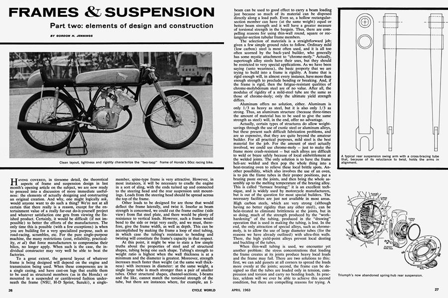
Attention to insuring rigidity is also necessary in the suspension. Most specials will be provided with a front suspension, usually telescopic forks, lifted right from some existing motorcycle — and that isn’t a bad idea at all. Still, the rear suspension will have to be fabricated, and it should be worth our while to say a word or two about that. Sometimes, the pivot bearings will be mounted in a large-diameter tube linking the two arms, and the pure torsional strength of the cross-tube will insure that the arms move together. A more convenient method, and a better one when the rear wheel is back some distance from the pivot, is to weld a cross-tube right in front of the wheel, leaving just enough clearance to allow for tire expansion with speed, or for a bigger-section tire if that should be needed. The idea is to hold the leverage of the swing arms acting on the cross-tube to a minimum. And, because of the leverage effect, the loads are heavier nearer the pivot, which presents us with a good case for tapered arms. Tapered tubing being a trifle scarce, it seems likely that the best approach, if you feel like taking the trouble, is to make the arms out of folded sheet steel, which can be formed to give the desired change in section depth and width.
For the ultra-ambitious builder, who feels a great compulsion to construct his own front suspension, we have little at this time but sympathy. Such a project is so involved, and so fraught with possibilities of terrible failure, that we will not even attempt to go into the matter at this time. The subject, along with a discussion of rake and trail, will be covered in a full-scale article on that alone in an article which is now being prepared and which will be along in the near future.
Springing is something about which there is a great deal of confusion. Basically, the idea is to provide springs that will give the lowest ride rate without allowing the suspension to bottom under the highest anticipated loads; which is another way of saying that the springs should be just as soft as circumstances will allow. Stiff springs will not only cause the rider an excessive amount of direct discomfort, from the sharp jouncing he gets in running over bumps, but it will cause the bike to bang along over the tops of bumps, with little adhesion between tires and road and this can cause the rider to fall, which is almost always very uncomfortable indeed. What is really needed is a set of springs that give a very soft ride at limited wheel deflections, but gets progressively stiffer as the suspension moves toward its stops.
Characteristics of this type are easily stated, and very hard to come by. The conventional spring has a set rate of closure with load, and if 100 pounds close it an inch, then another 100 pounds will close it another inch, giving it the same stiffness at all lengths until it bottoms. Fortunately, the spring can be wound with the coils closer together at one end, so that as it deflects some of the coils bottom and shorten the effective length of the spring, which makes it stiffer. Springs of this type have to be wound to order.
Suspension damping is a matter of compromise too: too little and the suspension bobbles uncontrollably; too much and it will be so harsh that the wheels do not maintain their contact with the road. The proper amount will be determined only by experimentation.
In selecting a wheelbase, fork-angle and trail, it would be most wise to pick an existing motorcycle with handling that you fancy. Then, copy its basic dimensions and weight distribution — not neglecting the weight of the rider. This will spare you the agony of sorting out these factors for yourself. And, in designing, do not forget such things as ground clearance and lean angle. The former is most important on scramblers, where too little can be a bother, but the latter is actually the more difficult to design into a machine. In any event, grounding some part of the bike when all leaned over presents the greatest hazard to life and limb, and it should be a matter of concern to the designer of a road-racing bike. The F.I.M. requires that the unladen bike be able to lean over at 50 degrees before grounding, and we would recommend that as a minimum. With modern tires, cornering is possible when over almost horizontal, and you will want the pipes, etc., tucked well up out of the way.
Weight distribution is important vertically, as well as along the wheelbase. A machine with its weight concentrated near the ground will be quick and responsive, but a high center of gravity provides the best stability. Strange though it may seem, this is true. Consider, if you will, the problem of balancing a long rod, with a weight at one end, on the tip of one’s finger: it will be easy to do if the rod is balanced with the weight uppermost; almost impossible with the weighted end down. The motorcycle presents an analogous situation : the rider is actually steering the wheels to keep them under the bike; if he fails to do so, it will fall, and the job is easier if the weight is well above the tire contact point. Of course, great care must be taken that this is not carried too far. It is entirely possible to get a finished machine that is most reluctant to leave a straight line or, once leaned over, to return to a vertical position.
We have purposely avoided a discussion on how one decides what size of tubing, with what wall-thickness, is to be used. In the absence of an engineering degree, or its equivalent, these things must be decided upon empirically; make a study of what others have done, and what has proven to be acceptable, and then proceed from there. Any good library can supply you with books that explain elementary stress analysis, and give formulae for finding the strength of tubes, I-beams, etc., and although it will involve a lot of hard thought, and endless figuring, you will be able to determine within reasonable limits, how strong your proposed frame will have to be and what will be needed to get that strength. A grasp of trigonometry is essential to this kind of investigation, and those of you who were unwise enough to only gargle at the fountain of knowledge in your school-days are going to regret it now. An instinctive “feel” for what is structurally correct and safe is fine, but it runs a poor second to actually knowing. Lacking this, you can only build to a wide margin of safety, following closely existing designs, and accept the penalty in excess weight.
Among currently produced motorcycles, we would rate the Norton Manx-derived models as being the best suspended and having the best frame — a rating that will surprise no one who reads CYCLE WORLD. It is not a design that can be universally applied, and we are not so struck by the design that we imagine it could not be improved upon, but it is still the best now in existence.
Not far behind the Norton, and much less expensive to manufacture, are the double-cradle frames used by Harley-Davidson, BSA, Triumph, Matchless/AJS, et al for their large-displacement models. Some of these use a double-tube brace along the top of the frame leading to the steering head, which is an excellent idea.
In the lightweight ranks, the Japanese bikes rate very highly. It is difficult to say which of them is the best; they all show signs of careful engineering, and we like the widespread Japanese used of pressed-steel lugs at tube junctions. These are lighter than castings of the same strength.
Some lightweights, 250cc and smaller, get by with frames that are essentially single-loop in layout. These can be quite successful when the upper member is sufficiently rigid, and functions as a strong backbone, with the lower part of the loop used mostly to support the engine. Even so, a more efficient disposition of members could make them slightly lighter. But, in most instances, the frame would weigh so little in any form that there is not much room for weight savings.
We realize that this article has probably raised as many questions as it has answered, and that was part of our intent in embarking on the project in the first place. Few motorcyclists will be so inspired that they would start right in on a machine of their own design, even if this article furnished complete instructions for that kind of thing — and it did not. Still, it should serve to create a better appreciation of the thought that has gone into each rider’s own machine, and to make him more aware of why things are as they are; if it does that, it will have served its purpose. •