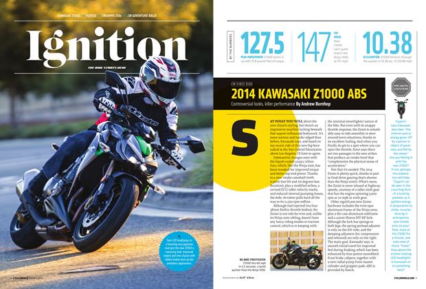
Shape And Stress
SHAPE AND STRESS
IGNITION
TDC
THE SCIENCE OF STIFFNESS AND STRENGTH
KEVIN CAMERON
A material basic to much manufacturing is rolled sheet or plate. We can crudely model it with paper and scissors. Cutting a narrow strip and pulling on its ends reveals good tensile (pulling) strength. But when you push the ends together, the material buckles immediately. Fighter pilots in World War II reported seeing the upper skin of their wings thrown into waves by such compressive budding during high-G pullouts. The skin on the bottom of the wing is under high tension, pulled tight and smooth.
If we now fold our paper strip lengthwise at right angles, we’ve made the equivalent of an “angle iron.” The fold doesn’t change its tensile strength, but when we push the ends together, the fold stiffens the paper, making it resist buckling a bit better. If we fold the strip one more time, we get a U-beam; it has fair bending strength and buckling resistance but resists twisting poorly. Structurally, it is a box without a top. We have all been impressed with how much stiffer a cardboard box becomes once its top is closed and taped. I once drew a swingarm this way—top, bottom, and sides were thin floppy sheet metal, causing the fabricator to say it could never work. But once welded together it became extremely stiff.
For even better compressive resistance, we could fold our paper strip lengthwise three times to make a box beam. Now each of its four faces is braced against buckling by two others. Old-time steel truss bridges on county roads had their top members made this way (riveted box beams) because, just as with the upper surface of an airplane’s wing, when a load is applied to the bridge the upper members are placed in compression. Box construction keeps the plate material in those beams self-braced against buckling. When Kawasaki in the 1980s built its KR500 GP bike, the engineers chose a box beam for its chassis.
Instead of making a box beam, we could roll our paper strip into a tube.
At some time in our early lives we have played with paper or plastic straws (to the consternation of parents, who had not expected lunch to become a series of structure experiments). A straw standing on a table can support a remarkable vertical (compressive) load before some portion of its length flattens, loses bending strength, and kicks sideways in collapse. Like the corners of a box beam, the tube’s curvature is self-bracing against buckling. Engine pushrods, which in dragracing must support dynamic loads of many thousands of pounds, are tubular for this reason.
Another approach to bracing a flat strip against easy bending is to stabilize its edges against buckling by attaching other strips to make an I-beam. When we support this from its ends we can see why it is so often used in construction. Its three elements are the vertical web (our original paper strip) and its horizontal top and bottom flanges.
All three brace one another against buckling under load, and when load is applied somewhere along its length (as in the wing or bridge mentioned earlier) the flange on the bottom resists tension, the flange on the top resists compression, and the web that joins them carries load in shear.
Webs carrying shear load are always on view on busy highways in the form of visible tension and compression in the vertical thin sheet-metal sides of box trailers. They are constructed as a box-beam (which is an I-beam with two shear webs; the floor of the trailer is the bottom flange, the roof is the top flange, and the thin sheet metal sides are its two shear webs). On a loaded trailer you can see lines of tension in the webs pointing diagonally down and toward the center, with ripples of buckling at right angles to them.
Ducati’s steel tube trellis frames are just special-purpose bridges. Their upper and lower horizontal tubes resist compression and tension (which reverse when you brake hard, throwing the top members into tension and the lowers into compression). Upper and lower tubes are connected by diagonal tubes, performing the function of the truck trailer’s shear webs and giving the structure strong resistance to “parallelogramming.”
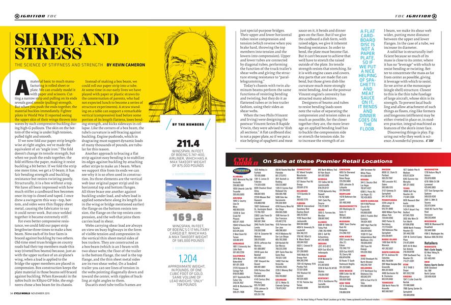
BY THE NUMBERS
211.4 WINGSPAN, IN FEET, OF BOEING’S 747-400, AIRLINER, WHICH HAS A MAX TAKEOFF WEIGHT OF 875,000 POUNDS
169.8 WINGSPAN, IN FEET, OF BOEING’S C-17 MILITARY CARGO JET, WHICH HAS A MAX TAKEOFF WEIGHT OF 585,000 POUNDS
1,204 APPROXIMATE WEIGHT, IN POUNDS, OF ONE CUBIC F00T0FG0LD. SAME VOLUME OF LEAD WEIGHS “ONLY” 708 POUNDS
Today’s chassis with twin aluminum beams perform the same functions of resisting bending and twisting, but they do it as flattened tubes or in box-trailer fashion, using their sides as shear webs.
When the two Phils (Vincent and Irving) were designing the postwar Vincent Series B Rapide V-twin, they were advised to “dish all sections.” A flat cardboard disc is not a paper plate, so if we put a nice helping of spaghetti and meat
sauce on it, it bends and dinner goes on the floor. But if we give the cardboard a dish form, with raised edges, we give it inherent bending resistance. In order to bend, the plate must become flat. But it can’t because to achieve that we’d have to stretch the raised outside of the plate. Its tensile strength resists that stretching. So it is with engine cases and covers. Any parts that are made flat can bend, but those given dish-like curvature much more strongly resist bending. And so the postwar Vincent engine’s convexity has attracted many admirers.
Designers of beams and tubes to resist bending loads soon note the value of separating the compression and tension sides as much as possible, for the closer together they are, the more leverage an applied bending load has to buckle the compression side or stretch the tension side. So to increase the strength of an I-beam, we make its shear web wider, putting more distance between the upper and lower flanges. In the case of a tube, we increase its diameter.
AFLAT CARDBOARD DISCIS NOTA PAPER PLATE, SO IF WE PUT A NICE HELPING OF SPAGHETTI AND MEAT SAUCE ON IT, IT BENDS AND DINNER GOES ON THE FLOOR.
A solid bar is structurally inefficient because so much of its mass is close to its center, where it has no “leverage” with which to resist bending or twisting. Better to concentrate the mass as far from center as possible, giving it leverage with which to resist.
So we arrive at the monocoque (single shell) structure. Closest to this is the thin tube fuselage of large aircraft, whose skin is its strength. To prevent local buckling and allow attachment of such things as floors, ring-like formers and longerons (stiffeners) may be either riveted in place or, in modern practice, integral-machined as features of the skin’s inner face.
Discovering things is play. Figuring out why they work is science. A wonderful process.
More From This Issue
-
 Up Front
An Oily, Fractured Journey
November 2015 -
 Intake
Intake
November 2015 -
 Ignition
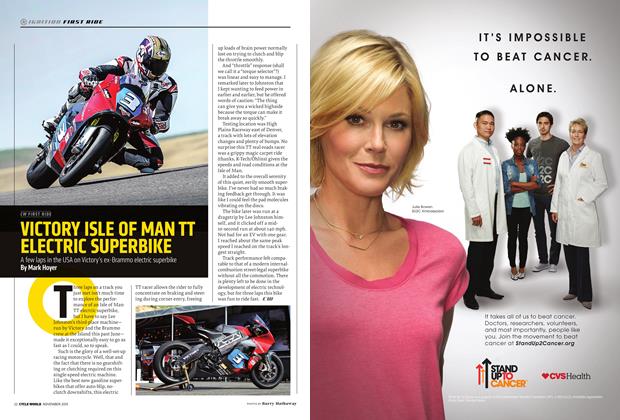
Victory Isle of Man Tt Electric Superbike
November 2015 -
 Ignition
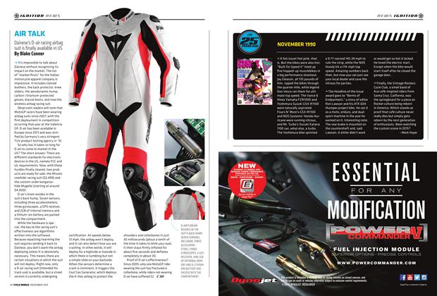
Air Talk
November 2015 -
Ignition
Cw 25 Years Ago November 1990
November 2015 -
 Ignition
On the Record Esteve “tito” Rabat 2014 Moto2 World Champion
November 2015