Technical Report Part Ii: the Reed Valve
THE REED VALVE
TECHNICAL REPORT PART II
Yamaha's adoption of reed induction upgrades low-rpm performance
DALE HERBRANDSON
YAMAHA'S ADOPTION of reed induction in 1972 has added a distinctive choice of engine design approaches for the motorcyclist. Reed induction has allowed Yamaha to use several unusual departures from the classic piston-ported engine layout. Briefly, here are the engine design changes prompted by the reed valve.
The production reed valve Enduro and MX engines for '72 have better tractability and greater peak power than their 1971 piston-ported rivals. Obtaining both of these objectives is quite a design achievement as there has been no sacrifice in engine reliability.
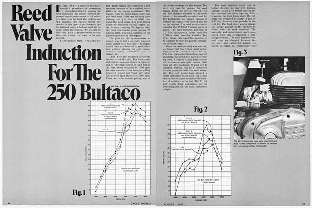
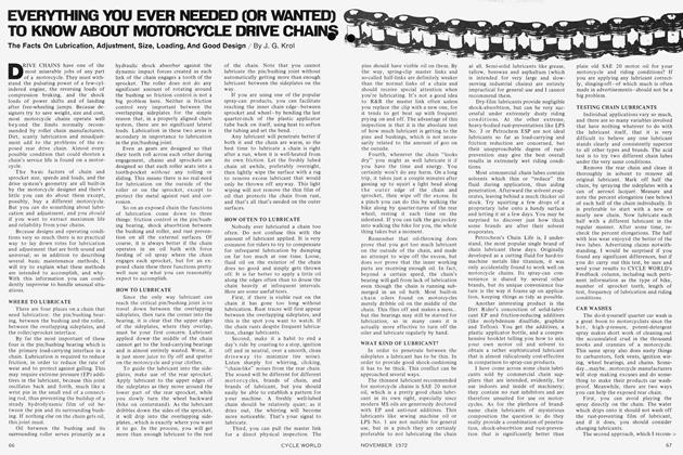
The power curve below for the 360 single-cylinder engine compares the output at the crankshaft. Note that reed valve engines have better power at every value of engine rpm. The peak output for the MX engine was raised from 30.4ps to 34ps (34 metric horsepower equals 34.6 bhp in U.S. terms). The port height and widths on the 1972 MX 360 are the same as the 1971 piston-ported engines.
The only significant change to the '72 porting is the addition of a 20mm wide "boost port" at the rear of the cylinder. This port is the same height as the other four transfer passages. Because of this porting addition, the reed valve engine has around 20 percent more total transfer port width than the 1971 version. This significant gain in port area accounts for the improved top end performance of the engine. It would be impossible, however, to add this port to the conventional piston-timed engine.
The reed valve is responsible for the upgraded low-rpm performance. Briefly compare reed induction against last year's design. The piston-ported intake track will have some reverse flow through the carburetor when running at low rpm and full throttle. This mixture which spits back out of the carburetor causes the inside of the air cleaner to become wet with fuel. This wetness is not really a problem, though. The loss of power accrues from that portion of the air/fuel mixture which passes through the carburetor more than once. The air picks up fuel with each pass through the carburetor—the resulting air/fuel mixture becomes too rich for best power. Radical inlet timing on the piston-ported engine is so detrimental to low end performance that many engines will load up and refuse to run in this speed range. The reverse flow also reduces the amount of mixture retained in the crankcase, and adds to the contributors in the power loss column.
Reed induction functions as a simple check valve and prevents reverse flow in the inlet track. The reed engine at low rpm has good air flow with the proper air/fuel ratio. Reed engines can be lugged down to very low rpm without any problems. Because of the more accurate control of inlet air at low rpm, carburetor pilot jetting has been changed on the reed engines. The pilot jet, which meters the fuel at low engine speed and partial throttle, must be larger than that found on piston-ported engines. Poor throttle response and overheating result from too small a pilot jet. This must not be overlooked when the '71 engines are upgraded to the '72 configuration.
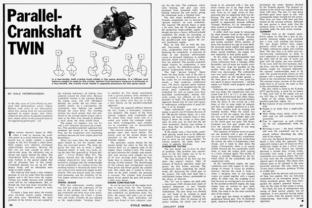
Incidentally, both of the latest 360 barrels will back fit the 1970 and 1971 crankcases for a very easy conversion. The 250 engines present a problem. The 1972 con rod and cylinder are 5mm shorter than previous models. The reed valve cylinder cannot be bolted directly to '71 and older crankcases without using either a 5mm spacer or fitting the shorter con rod.
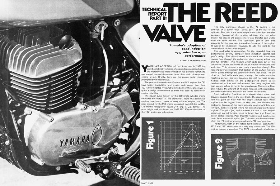
Figure 2 shows the auxiliary transfer passage which is fed from the reed valve cavity. Note that there was no attempt to "stuff" this cavity. The opening in the rear of the cylinder, when matched against the piston, shows us that this extra port is not fed from the crankcase. The boost port is fed from the pressure rise created downstream from the reed valve when the piston nears bdc and shuts off the intake passage into the crankcase. The inertia of the incoming air/fuel mixture in the inlet tract is responsible for the flow through the boost port in the reed valve barrel.
Dyno testing, which I have done on engines one-third the displacement of the 360, shows an interesting tuning effect when the piston forces the intake flow to be diverted from the crankcase to the boost port. More top end power is created by isolating this port from the crankcase, as done in the stock 360 engine. A simple modification is possible which alters the torque curve. For example, if another hole were cut into the piston above the pair already shown in Figure 2, we would gain low end power while sacrificing top end output. The boost port in this instance would always experience crankcase pressure. If the third hole, which must line up with the boost port in the cylinder, were placed just under the second piston ring, cool gases would circulate under the piston crown. This cooling effect is beneficial to piston life under desert riding conditions. A comparison of the two porting approaches is shown below for a 125cc engine—the ideas are applicable to the 360. The piston sketched on the graph has two top holes because the engine used a pair of boost ports separated by a 6mm wide bridge.
The tuner should exercise some restraint when porting the reed valve barrels though. The boost port has quite an influence on the power curve of the engine when the top set of holes is not used in the piston. If the boost port is made very wide (but no higher) the engine becomes peaky. The loss of usable rpm is accompanied by a large increase in power. The resulting machine would be fast, but uncomfortable to ride because of the narrow power band. On the dyno, I have increased the output of an engine by over 10 percent by just working on the width of the boost ports. The tuner should slowly work out the port shapes with much testing inbetween trials.
The piston illustrated in Figure 2 is the same as the 1971 design except for two things. First, the piston skirt has been ventilated with a pair of 16mm diameter holes. The holes allow the reed valve to experience the depression in crankcase pressure just after the piston moves from the bdc position. The resulting long breathing period gives reed induction an advantage over the conventional piston-timed inlet. These holes appear to be quite conservative in the interest of piston strength.
Secondly, the 1972 piston uses a new piston ring design. The top ring at first glance is a conventional Dykes ring. However, close examination shows that the bottom surface of the piston ring is finished on a 7-degree angle as shown in Figure 5. The design is said to reduce the tendency of ring sticking under racing conditions. This Keystone fire ring design has been patented by Japan's Nippon Piston Ring Company, and is used on the 360 and 250 engines. All other reed engines for '72 use last year's trapezoid-shaped Keystone ring for a fire ring. It is flat on the bottom and chamfered on top.
THE REED VALVE
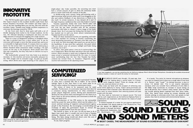
The reed valve assembly is most interesting, for it incorporates a clever design which promotes long reed life. All models use stainless steel reeds which close against a rubber coated manifold. The purpose of the rubber is to cushion the impact when the reeds close. The cushion is required to prevent the edges of the reeds from chipping away. Persons familiar with reed induction can recall engines which use steel reeds directly on an aluminum reed block. They are easy to remember because of the messy engine damage caused by the debris created by the eroding reed petal. This design can still be found on many outboard engines. It is a good design for low rpm engines, for the breakage only comes with high rpm. Yamaha's rubber-coated reed block has eliminated this source of reed failure on their high rpm engines. In fact, Yamaha does not even offer individual replacement reeds for sale—that's confidence! The reed petal thickness is 0.008 in. for the 250 and 360 engines, which have identical reed valve assemblies.
Everything mentioned so far has been concerned with the 360 and 250 engines. A 175, 125 and 100 are also available with reed induction. The 175 and 125 share an interchangeable reed valve assembly. The shape of the reed is shown in Figure 7, in contrast to the other two designs already this year by Yamaha. The power curves for these two engines have been upgraded with the improvements afforded by Torque Induction. Except for the magnitude of the power produced, the general shape of the curves for these two machines is about the same as shown in Figure 2. The engines have a good torque band and are easy to keep "on the pipe."
The unusual engine for '72 is the 100cc Single, identified as an LT series. This reed valve engine replaced the 90cc piston-ported HT series here in the U.S. An Enduro and MX state of tune are offered. Not much hardware for the 100 was offered by Yamaha for this article (See Dec. '71 CW test report). They did, however, offer a power curve delineating the output at the engine crankshaft. The power difference between the Enduro and MX racing engine is unreal. The MX engine puts out 17.3ps at 10,800 rpm. Because of the reed induction this little screamer is not bothered with the low speed "loading up" problem of a similarly tuned piston-ported engine.
CONCLUSIONS
Torque Induction is well named as the 1972 reed valve engines have a generous amount of torque which is available over a surprising rpm range. The reed engines are comfortable to operate as the improved breathing and air/fuel ratio at low rpm gives good throttle response. For the heavily modified engines, the absence from the tendency to load up at low rpm is most welcomed in trials and motocross events. The extra margin in engine tractability, plus the improved top end performance, makes the Yamaha reed engines outstanding contenders.